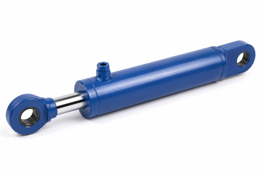
Why do OEM projects fail when buyers order only by cylinder size?
Buying a cylinder only by bore, stroke, and mounting style is risky because the cylinder is only one part of the motion chain. If pump flow, valve metering, hose routing, oil cleanliness, and load direction are not checked together, the machine may lift correctly in a sample test but move unevenly, overheat, drift, or become difficult to control in production.
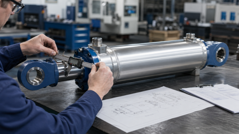
A common OEM mistake is to send a drawing with “80 mm bore, 50 mm rod, 400 mm stroke” and assume the supplier can quote a finished solution. Those numbers describe the actuator envelope, but they do not confirm cycle speed, pressure reserve, side-load risk, seal compatibility, duty cycle, or port orientation. For an equipment designer, that gap becomes a commissioning problem. For a buyer, it becomes a hidden cost after the purchase order is placed.
The practical decision logic is direct: if the cylinder must move smoothly, confirm pump flow, valve control, hose size, and load before finalizing the cylinder. In a compact lifting platform, for example, a cylinder with sufficient force can still extend too slowly if pump displacement is undersized. The same cylinder can jerk if the directional valve has poor metering or if the hose size causes excessive pressure loss.
ZHY normally treats the cylinder as part of a hydraulic actuator system, not as an isolated steel tube. That means the quotation stage should include basic system questions, especially for OEM equipment where repeatable performance matters more than one-time installation.
Key Takeaways
- A cylinder dimension does not define machine speed; flow rate, oil path, and valve metering do.
- Force is calculated from pressure and piston area, but stability also depends on load direction and mounting geometry.
- For OEM equipment, the safest early request is a system parameter check before sample production.
- ISO 4413 requires hydraulic systems to consider safety, pressure control, leakage, temperature, and maintenance access.
- The best supplier discussion includes load, cycle time, pressure range, working environment, and expected production volume.
Which system parameters should be confirmed before selecting a cylinder?
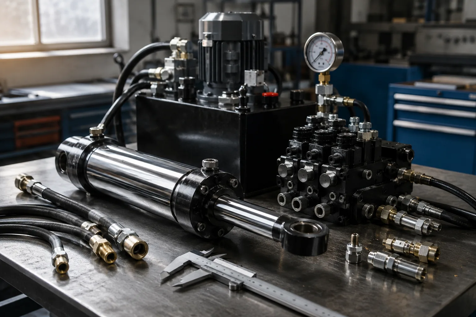
The minimum selection package should include load, working pressure, required speed, stroke, mounting method, valve type, hose length, oil temperature, duty cycle, and operating environment. These inputs let the supplier judge whether the cylinder, power unit, valves, and oil path can work as one controlled system rather than as disconnected components.
Force is the easiest number to calculate, but it is not enough. The extension force of a double-acting cylinder is based on pressure multiplied by piston area, while retraction force is lower because the rod area reduces the effective area. Speed is driven by flow rate and cylinder volume. A larger bore increases force, but it also needs more oil per millimeter of travel, so the same pump may produce slower movement.
For equipment designers, the most useful early check is a small parameter table in the request for quotation. Instead of asking only for a drawing match, ask the supplier to verify whether the proposed valves and cylinders match the desired motion profile. If the equipment needs slow, stable lifting, a flow control valve or proportional valve may matter more than a larger cylinder body.
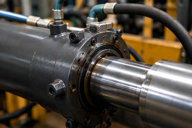
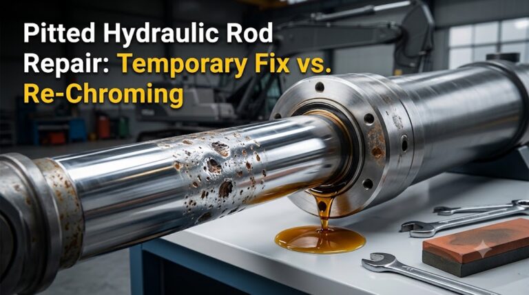
Material and surface choices also belong in the system discussion. Common cylinder barrels use honed steel tubing; rods are often chrome-plated or induction-hardened depending on wear exposure; seals must match oil type and temperature. For corrosive environments, rod coating and wiper design deserve attention before the first prototype is built.
- Bore
- The internal cylinder diameter that mainly determines output force at a given pressure.
- Stroke
- The usable linear travel of the rod, which must match the machine linkage and end-position clearance.
- Flow rate
- The oil volume delivered per unit of time; it has a direct effect on extension and retraction speed.
- Relief valve
- A pressure-limiting valve used to protect the hydraulic circuit from overload conditions.
How should buyers match cylinders, pumps, valves, and hoses?
Start from the motion requirement, not the component catalog. A good match begins with the required force and cycle time, then works backward to pressure, cylinder area, pump flow, valve control, hose size, and thermal behavior. This sequence prevents a technically strong cylinder from being installed in a weak circuit.
| Situation | Main risk if ignored | Recommended check | Preferred buying action |
|---|---|---|---|
| Heavy load with short cycle time | Slow extension, high oil temperature, relief valve opening too often | Calculate cylinder volume, pump flow, duty cycle, and pressure reserve | Ask for cylinder and power-unit compatibility review before sampling |
| Precise or smooth positioning | Jerky movement, overshoot, inconsistent stopping position | Review valve metering, flow control, load holding, and air bleeding method | Specify the motion profile instead of only listing bore and stroke |
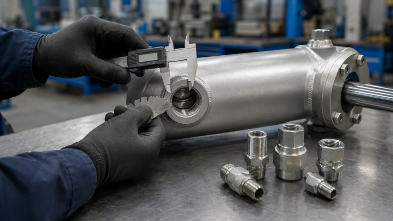
| Long hose runs or compact routing | Pressure drop, heat generation, delayed response, hose abrasion | Check hose internal diameter, bend radius, routing clamps, and fittings | Request a hose and port layout review with the cylinder drawing |
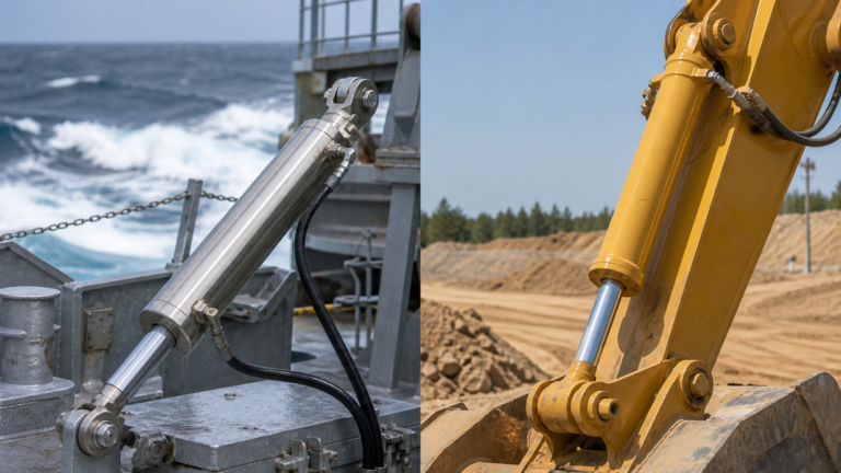
| Outdoor or dirty operating environment | Rod corrosion, seal wear, contamination entering the system | Confirm rod coating, wiper style, seal material, and filtration practice | Use an environmental requirement sheet during supplier evaluation |
| OEM batch production | Sample works, batch units vary in speed or fit | Check tolerances, port consistency, packaging protection, and test records | Approve a documented inspection plan before mass production |
How to use this table: use the “Situation” column to identify the dominant engineering risk, then prioritize the “Recommended check” before comparing price. If two rows seem equally important, choose the row linked to safety or machine downtime first, because those failures are more expensive to correct after assembly.
What performance and compliance issues matter in real equipment?
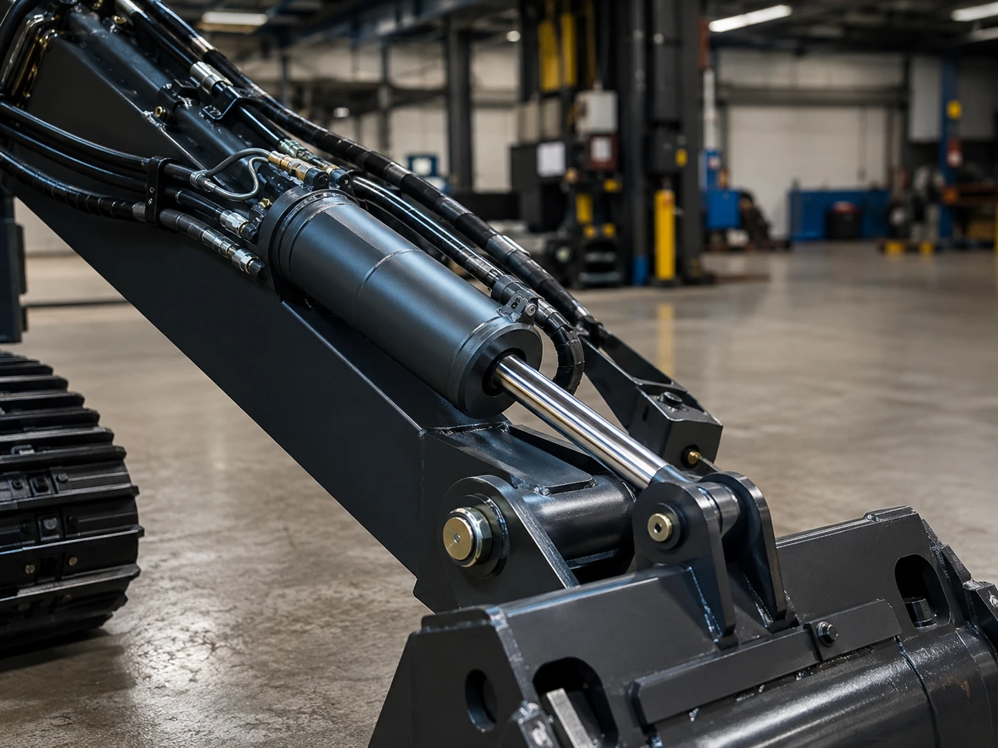
Real equipment adds side load, contamination, vibration, temperature change, and operator behavior to the calculation. A cylinder that performs well on a clean test bench may suffer seal damage or unstable speed when installed at an angle, exposed to dust, or connected to a poorly controlled valve circuit.
ISO 4413 is one of the core references for hydraulic fluid power safety. It addresses system-level requirements such as pressure control, component selection, maintenance access, protection against hazards, and safe energy isolation. For OEM buyers, the key lesson is that hydraulic safety is not created by the cylinder alone; it is created by the complete circuit and machine design.
Standards for mounting dimensions, such as ISO 6020-2 for 16 MPa compact series cylinders and ISO 6022 for 25 MPa series cylinders, help designers standardize envelopes and interfaces. These standards do not remove the need to verify load, speed, contamination control, and seal life, but they reduce interchangeability and drawing confusion in industrial applications.
Industry trends also affect selection. Compact hydraulic power units, electrified mobile equipment, and space-constrained attachments are pushing designers toward smaller reservoirs, tighter hose routing, and more integrated valve blocks. That increases the importance of early thermal review and contamination control. A modern hydraulic power unit cylinder package is often judged by noise, efficiency, smoothness, and service access, not only by maximum force.
What should OEM buyers ask suppliers before prototype approval?
Before approving a sample, buyers should ask suppliers to prove fit, force, speed logic, sealing choice, surface protection, testing method, and batch control. The goal is not to make the supplier redesign the whole machine; it is to prevent avoidable mismatch between the cylinder and the rest of the hydraulic circuit.
A serious supplier should be able to comment on the drawing, but also on operating assumptions. Ask whether the proposed port size may restrict flow. Ask whether the rod coating is suitable for outdoor exposure. Ask whether the seal package matches the expected oil and temperature. Ask whether the cylinder will be tested for leakage and pressure before shipment.
ZHY can support this stage by reviewing cylinder drawings together with system parameters. For a buyer at the top of the funnel, the most valuable first step is not a final quote; it is a short technical confirmation that the proposed cylinder belongs in the intended equipment design.

Practical asset: OEM hydraulic cylinder parameter checklist
- Define the motion first: write the required stroke, extension time, retraction time, holding time, and acceptable speed variation before discussing cylinder price.
- Record the load condition: provide maximum load, normal working load, load direction, linkage ratio, shock load possibility, and whether the cylinder will push, pull, lift, clamp, or steer.
- Confirm the power source: ask what pump flow, working pressure, relief valve setting, reservoir size, and duty cycle will be used with the cylinder.
- Check valve control: identify whether the circuit uses manual directional valves, solenoid valves, proportional valves, counterbalance valves, flow controls, or load-holding valves.
- Review oil path details: request comments on port size, hose internal diameter, hose length, bend radius, fitting type, and whether pressure drop may affect movement.
- Specify the environment: state indoor or outdoor use, dust level, water exposure, salt exposure, temperature range, vibration, and maintenance interval.
- Ask for material and seal choices: request barrel material, rod surface treatment, seal material, wiper type, and compatibility with the planned hydraulic oil.
- Require test evidence: ask for pressure test, leakage check, stroke check, appearance inspection, and packaging method before batch shipment.
- Approve one controlled sample: test the sample on the real machine, record speed, noise, heat, drift, and operator feel, then freeze the drawing and inspection standard.
FAQ
1. What is included in a hydraulic cylinder system?
A hydraulic cylinder system normally includes the cylinder, pump or power unit, reservoir, directional valve, pressure relief valve, hoses, fittings, filtration, hydraulic oil, and control elements. The cylinder converts oil pressure into linear force, while the pump and valve circuit determine how fast and how smoothly it moves. ISO 4413 treats hydraulic equipment as a system because safety depends on pressure control, component selection, maintenance access, and energy isolation, not only on actuator strength.
2. How do I calculate whether a cylinder has enough force?
Basic cylinder force is calculated from hydraulic pressure multiplied by effective piston area. Extension force uses the full piston area, while retraction force is lower because the rod area subtracts from the effective area. Designers should also allow margin for friction, linkage geometry, shock load, pressure loss, and relief valve behavior. A force calculation proves theoretical capacity, but it does not prove stable motion. Speed, valve control, hose sizing, and mounting alignment still need separate checks.
3. Why can a correctly sized cylinder still move too slowly?
A correctly sized cylinder can move too slowly when pump flow is too low for the cylinder volume, when hoses or ports restrict oil flow, or when valves are not suited to the desired motion profile. A larger bore increases force, but it also increases the amount of oil needed for each stroke. This is why OEM buyers should provide cycle time and pump data when asking for a quote, not only bore, rod, and stroke dimensions.
4. What standards are useful for hydraulic cylinder selection?
ISO 4413 is useful for hydraulic system safety requirements, while ISO 1219 helps standardize graphical symbols and circuit diagrams. ISO 6020-2 and ISO 6022 are relevant for certain standardized industrial cylinder mounting dimensions and pressure series. These standards help reduce ambiguity, but they do not replace application review. A supplier still needs the actual load, speed, environment, oil type, and mounting condition to recommend a cylinder that performs reliably in the final equipment.
5. When should an OEM buyer involve the cylinder supplier?
An OEM buyer should involve the cylinder supplier before prototype approval, ideally when the machine layout, load, pump, valve concept, and mounting envelope are still adjustable. Early involvement helps identify port restrictions, rod protection needs, seal concerns, and speed mismatch before tooling or batch purchasing begins. Suppliers such as ZHY can review the cylinder drawing with system parameters, which is more useful than quoting after all design decisions are already fixed.
References
- ISO 4413:2010 Hydraulic fluid power — General rules and safety requirements for systems and their components, International Organization for Standardization, ISO, 2010.
- ISO 1219-1:2012 Fluid power systems and components — Graphical symbols and circuit diagrams — Part 1: Graphical symbols for conventional use and data-processing applications, International Organization for Standardization, ISO, 2012.
- ISO 6020-2:2015 Hydraulic fluid power — Mounting dimensions for single rod cylinders, 16 MPa (160 bar) series — Part 2: Compact series, International Organization for Standardization, ISO, 2015.
- ISO 6022:2015 Hydraulic fluid power — Mounting dimensions for single rod cylinders, 25 MPa (250 bar) series, International Organization for Standardization, ISO, 2015.
- The Hydraulic Trainer, Volume 1: Basic Principles and Components of Fluid Power Hydraulics, Bosch Rexroth AG, Bosch Rexroth, 2008.
- Industrial Hydraulic Technology Bulletin 0232-B1, Parker Hannifin Corporation, Parker Hannifin, 2016.
- 29 CFR 1910.147: The control of hazardous energy, Occupational Safety and Health Administration, U.S. Department of Labor, 1989.
- Hydraulic Hose, Fittings and Equipment Technical Handbook, Gates Corporation, Gates, 2021.
How should designers and buyers think about the complete hydraulic actuator decision?
The best way to understand a hydraulic cylinder system is to treat it as a controlled energy path. Oil leaves the pump, passes through valves, moves through hoses and ports, enters the cylinder chamber, acts on piston area, and finally creates machine motion through pins, bearings, and linkages. Every part of that path can improve or damage the final result.
For OEM equipment, the strongest buying option is not always the largest bore or the highest nominal pressure. Choose a larger bore when the design lacks force margin and the pump can support the required oil volume. Choose improved valve control when the complaint is jerky movement, overshoot, or poor operator feel. Choose better rod protection, wipers, and filtration when the environment is dirty or outdoor. Choose standardized mounting dimensions when interchangeability and future maintenance are important.
Regulatory and standards thinking should enter early. ISO 4413 reinforces that hydraulic systems require safe pressure control, suitable component selection, and maintenance planning. OSHA lockout requirements also remind equipment builders that stored hydraulic energy can create service hazards if isolation and release procedures are not considered. These are not abstract compliance points; they influence where test ports, relief valves, guards, and maintenance access should be placed.
The market direction is toward compact, integrated, and more efficient hydraulics, especially in mobile equipment, lifting devices, agricultural attachments, and automated fixtures. Smaller spaces make mismatch more visible. Heat, pressure drop, noise, and unstable motion appear quickly when designers compress the hydraulic package without reviewing the full circuit. That is why early parameter confirmation is becoming a procurement advantage.
The practical purchasing reason is simple: a supplier that confirms load, flow, valve, hose, and environment details can prevent problems that a drawing-only quote cannot see. ZHY’s role is best positioned at that point, where cylinder manufacturing knowledge meets system-level questions from equipment designers and buyers.