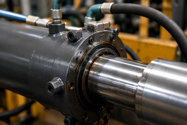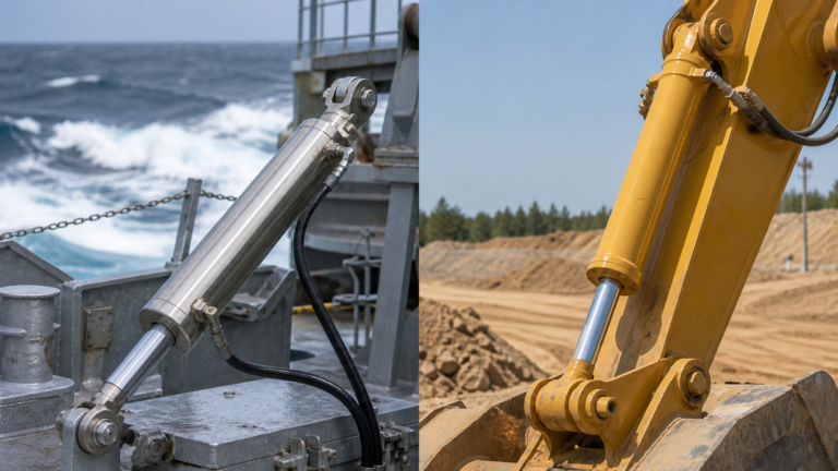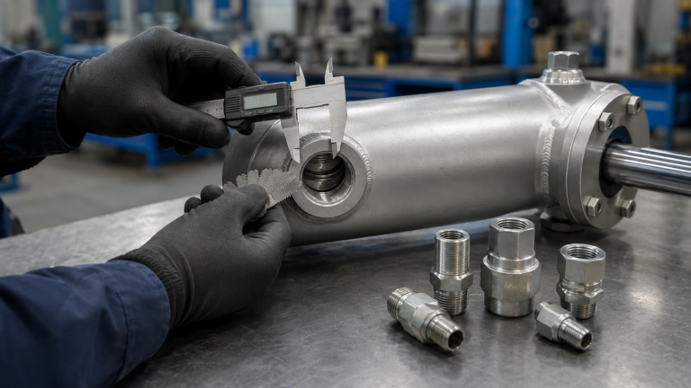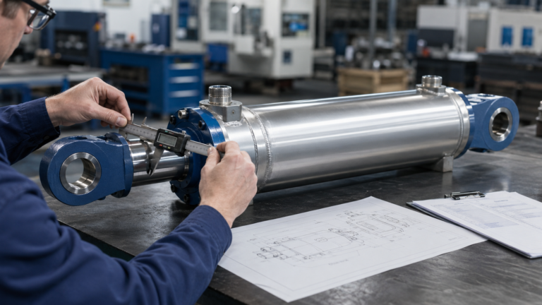
At that point, it is easy to blame the new cylinder.
Sometimes the cylinder is responsible. Sometimes it is not.
Hydraulic cylinder failure after installation can result from incorrect manufacturing, but it can also come from mounting misalignment, side loading, pressure spikes, contaminated hydraulic oil, incorrect dimensions, restricted hoses, or missing application information.
If you replace the cylinder without finding the real cause, the next cylinder may fail in exactly the same way.
This guide shows you what to check, how to separate an installation problem from a cylinder defect, and what information to prepare before ordering a corrected replacement.
Has Your New Cylinder Already Failed?
Send the drawing, installation photos, working pressure, failure location, and a short operating video. ZHY Hydraulic can review the likely cause before you order another cylinder.
Quick Answer: Why Do Hydraulic Cylinders Fail After Installation?
Hydraulic cylinders commonly fail after installation because the actual mounting, pressure, load, speed, oil condition, or operating environment differs from the conditions used when the cylinder was selected or manufactured.
The most common causes are mounting misalignment, side loading, incorrect closed length or stroke, pressure spikes, rod buckling, contaminated oil, incompatible seals, trapped air, restricted flow, and damage during installation.
Before you replace the cylinder, inspect the complete hydraulic system and machine structure. A pressure-tested cylinder can still fail when it is installed into a misaligned frame, connected to contaminated hoses, or subjected to forces that were not included in the original specification.
Hydraulic Cylinder Failure Symptoms at a Glance
The symptom usually gives you the first clue. Start with what you can see, hear, or measure before removing the cylinder.
| What You Notice | Likely Causes | What You Should Check First |
|---|---|---|
| Oil leaks around the rod seal | Side load, damaged rod, contamination, high return pressure, incorrect seal material | Rod alignment, rod surface, oil cleanliness, return-line pressure |
| The cylinder binds during part of the stroke | Misaligned mounts, bent frame, tight pins, side loading, mechanical interference | Alignment at retracted, mid-stroke, and extended positions |
| The rod bends near full extension | Buckling, excessive load, undersized rod, long unsupported length | Rod diameter, stroke, load direction, mounting arrangement |
| The movement is jerky or unstable | Trapped air, contaminated oil, poor alignment, valve instability | Bleeding, oil level, suction line, mounting alignment |
| The load slowly drops | Piston-seal bypass, valve leakage, counterbalance valve problem | Isolate the cylinder from the valve before deciding |
| The cylinder stops before completing the movement | Wrong stroke, wrong closed length, linkage interference, restricted flow | Installed dimensions and equipment movement |
| The mount, eye, or weld cracks | Shock load, twisting, side load, pin clearance, weak mounting structure | Load path, pin fit, bracket deformation, impact pressure |
| The cylinder or oil becomes unusually hot | Restricted return flow, internal leakage, high speed, undersized ports | Flow rate, hose size, valve size, return pressure |
Safety warning: Never loosen hydraulic hoses or mounting pins while the cylinder is holding an unsupported load. Lower or mechanically support the equipment and release stored pressure before inspection.
1. The Mounting Points Are Misaligned
The new cylinder may fit between the brackets without much trouble. Both pins go in. The hoses reach the ports. Nothing looks obviously wrong.
Then you operate the machine.
The rod begins rubbing against one side of the guide. Movement becomes tight near mid-stroke. After several cycles, oil appears around the rod seal.
What You Notice
- The cylinder moves smoothly when disconnected but binds after both ends are mounted.
- One pin is difficult to install or must be hammered into place.
- The rod seal wears more heavily on one side.
- The rod has a polished or scratched strip along one side.
- The cylinder becomes hotter during operation.
Why It Happens
A hydraulic cylinder is intended to transfer force along its centerline.
If the base mount and rod-end mount are not aligned, the cylinder must push or pull while being forced sideways. The rod, gland, guide bearing, piston, and seals then carry loads they were not designed to handle.
The alignment may look acceptable when the machine is unloaded. Under working load, however, the frame or bracket can bend and pull the cylinder off-axis.
How to Confirm It
Check the cylinder alignment in three positions:
- Fully retracted;
- At approximately half stroke;
- Near full extension.
Also inspect the mounting pins and bushings. Uneven wear on one side often shows that the load is not passing straight through the cylinder.
How to Prevent It
Do not confirm mounting fit only when the cylinder is retracted. Check the complete movement before applying full load.
Verify pin centers, bracket width, mounting angles, bearing freedom, and frame deformation. If the machine structure changes shape under load, the mounting design may need adjustment rather than another seal replacement.
2. The Cylinder Is Carrying Side Load
You replace the rod seal. The leakage stops.
Two weeks later, the same side of the seal begins leaking again.
At this point, another seal kit is unlikely to solve the problem.
What You Notice
- Leakage repeatedly appears on the same side of the rod.
- The guide bushing or wear ring has uneven wear.
- The piston rod has long scratches on one side.
- The cylinder feels tight at one position.
- The rod bends or develops visible runout.
Why It Happens
A cylinder sometimes becomes an accidental guide for the machine.
This happens when the equipment has worn pivots, insufficient guide rails, loose bearings, uneven loading, or a linkage that shifts sideways during operation.
The cylinder is then expected to create linear force and control lateral movement at the same time.
Standard rod seals and guide bearings cannot compensate for continuous external side load. Increasing seal hardness may delay leakage, but it does not remove the force that caused the damage.
How to Confirm It
Disconnect one end of the cylinder only after the equipment is safely supported. Check whether the linkage moves freely without pulling the cylinder sideways.
Inspect the rod guide, piston wear rings, seals, and rod surface. Wear concentrated on one side is a strong warning sign.
How to Prevent It
Repair worn machine guides, bushings, pivots, and brackets before installing another cylinder.
If angular movement is unavoidable, consider whether a spherical bearing, clevis, trunnion, or another mounting arrangement is more suitable.
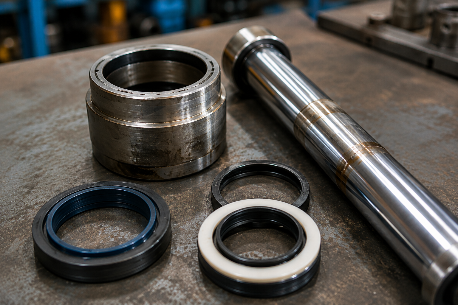
A correctly sized bore can still fail early when its mounting creates side load, pin binding, or angular misalignment. ZHY also considers these factors when reviewing hydraulic cylinder sizing and mounting geometry.
3. The Mounting Style Does Not Match the Machine Movement
Two cylinders can have the same bore, rod diameter, and stroke.
One works for years. The other begins cracking around the mounting eye.
The difference may be the way the cylinder follows the machine movement.
What You Notice
- The mounting eye, flange, or trunnion shows unusual wear.
- The cylinder twists while extending.
- Pins loosen or mounting holes become oval.
- Cracks appear near a welded mounting component.
- The cylinder fits but cannot pivot freely.
Why It Happens
The mounting style determines how force enters the cylinder and how the cylinder follows changes in the equipment angle.
A clevis mount allows pivoting. A spherical bearing tolerates limited angular variation. A trunnion lets the barrel rotate around a defined point. A rigid flange works best where the cylinder remains accurately guided.
Problems begin when the replacement copies the main dimensions but not the original movement.
For example, replacing a spherical bearing with a rigid plain bearing may make the cylinder cheaper. It may also transfer every small alignment error directly into the rod and gland.
How to Confirm It
Observe whether the cylinder must change angle during extension and retraction.
Check whether the mounting pins remain parallel throughout the movement. Look for seized bearings, tight brackets, incorrect trunnion positions, or mounts that receive twisting rather than straight push-and-pull force.
How to Prevent It
Specify the mounting type together with the equipment movement, not as an isolated drawing detail.
When ordering custom hydraulic cylinders manufactured from drawings or samples, provide photos showing the cylinder in both retracted and extended positions. This helps the manufacturer understand how the mounting actually moves.
A Drawing Shows Dimensions. Installation Photos Show the Real Load Path.
Send both when requesting a failure review. The combination makes it easier to identify alignment, mounting, and clearance problems before another cylinder is produced.
4. The Closed Length, Stroke, or Extended Length Is Wrong
The replacement cylinder arrives and fits between the mounting points.
That feels like success.
Then the machine cannot return to its original position. Or the linkage hits the frame before the piston reaches the end of its stroke.
What You Notice
- The equipment stops before completing its required movement.
- The piston reaches the cylinder end before the machine reaches its intended position.
- The linkage or structure becomes the mechanical stop.
- The cylinder fits when retracted but overextends the mechanism.
- The rod remains partly extended when the machine should be fully closed.
Why It Happens
Bore and stroke are not enough to confirm installation fit.
You also need the correct closed center distance and extended center distance. Rod-end threads, mounting eyes, clevises, spacers, cushions, and internal stops can all affect the final dimensions.
Another common mistake is measuring an old failed cylinder without checking whether it is bent, modified, or internally damaged.
How to Confirm It
Measure and record these values separately:
- Closed length: mounting center to mounting center when fully retracted;
- Stroke: the actual distance travelled by the piston;
- Extended length: mounting center to mounting center when fully extended.
Then compare them with both the approved cylinder drawing and the actual machine movement.
How to Prevent It
Do not approve a replacement drawing that shows only bore and stroke.
Confirm all mounting centers, pin dimensions, rod-end adjustment, port clearances, and the equipment’s mechanical end positions before production.
5. Actual Pressure Is Higher Than the Design Pressure
The pressure gauge says 18 MPa. The cylinder was designed for 21 MPa.
It looks safe.
But the mounting eye still cracks, the rod bends, or the seal extrudes after a sudden stop.
What You Notice
- Failure occurs during direction changes or sudden stops.
- The cylinder survives normal movement but fails under impact.
- Seals show extrusion or severe deformation.
- Ports, tubes, welds, or mounting components deform.
- The problem happens intermittently rather than every cycle.
Why It Happens
The normal gauge reading may not show short pressure spikes.
Peak pressure can occur when:
- A moving load stops suddenly;
- A valve closes too quickly;
- The piston reaches the end of stroke at high speed;
- The machine receives an external impact;
- A load overruns the cylinder;
- A relief or counterbalance valve is incorrectly adjusted.
The cylinder may therefore experience a much higher load than the operator sees during steady movement.
How to Confirm It
Measure pressure dynamically near the cylinder, not only at idle or during slow operation.
Record pressure during acceleration, direction changes, load holding, sudden stopping, and end-of-stroke movement.
How to Prevent It
Provide normal working pressure, relief-valve setting, known peak pressure, maximum load, and shock conditions before manufacturing.
For severe applications, review whether the cylinder requires heavier tube walls, stronger mounting components, a larger rod, cushioning, or improved valve control.
Heavy-duty cylinder selection should account for side load, abrasive conditions, shock, and mounting geometry rather than pressure alone. These risks are also addressed on ZHY’s heavy-duty hydraulic cylinder solutions page.
6. The Piston Rod Is Too Small for the Load and Stroke
The cylinder develops enough hydraulic force to push the load.
That does not automatically mean the rod can remain straight while doing it.
What You Notice
- The rod bends near full extension.
- The cylinder binds only under heavy compressive load.
- The rod seal begins leaking after the rod bends slightly.
- Wear becomes worse as the unsupported rod length increases.
- The same rod fails repeatedly after repair.
Why It Happens
A rod under compression can buckle.
The risk increases when the rod is long, thin, heavily loaded, poorly supported, or connected through mounting arrangements that allow greater effective length.
This is why two cylinders with the same bore and working pressure may need different rod diameters.
The bore determines hydraulic force. The rod must then carry that force without buckling, bending, or creating excessive deflection.
How to Confirm It
Review:
- Rod diameter;
- Stroke;
- Maximum unsupported extension;
- Compressive load;
- Mounting type;
- Load direction;
- Any existing side load or frame movement.
Do not inspect only the final bend. Also check whether the machine forced the rod sideways before it buckled.
How to Prevent It
Complete a buckling review for long-stroke or high-compression applications.
Possible corrections may include a larger rod, a different material, reduced unsupported length, revised mounting geometry, or improved external guidance.
Do not replace a bent rod with another rod of the same size until you understand why the first one bent.
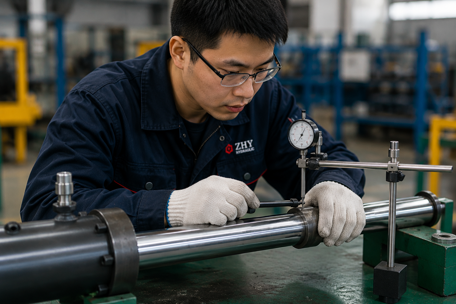
7. Contamination Enters the New Cylinder
The old cylinder failed internally.
You remove it, install the replacement, connect the original hoses, and restart the machine.
A few days later, the new cylinder begins leaking.
The new cylinder may have received the remains of the old one.
What You Notice
- New seals become scratched or cut shortly after installation.
- The oil contains dark particles, metal, or seal fragments.
- The rod or cylinder bore develops scoring.
- Valves begin sticking after the old cylinder failure.
- Filters become blocked unusually quickly.
Why It Happens
When an old cylinder fails, debris may remain in:
- Hoses;
- Valve blocks;
- The hydraulic tank;
- Filters;
- Manifolds;
- Coolers and return lines.
Contamination can also enter during installation. Open ports collect dust. Dirty hose ends introduce grit. Excess thread tape breaks off and enters the oil passage. Welding or grinding near the cylinder adds metal particles.
How to Confirm It
Inspect the oil, filter, damaged seals, rod, piston, and tube.
Particles embedded in seals or long scratches on sliding surfaces often point to contamination rather than normal wear.
How to Prevent It
- Keep cylinder ports capped until connection.
- Clean hose ends before installation.
- Flush the circuit after a destructive failure.
- Inspect or replace filters.
- Clean the reservoir where contamination is present.
- Prevent thread sealant from entering the oil passage.
- Use hydraulic oil with the required cleanliness and viscosity.
A new cylinder should not be used as the cleaning tool for an old contaminated hydraulic system.
8. The Seal Material Does Not Match the Application
The seal may be new. The dimensions may be correct. The cylinder may pass a factory leakage test.
It can still fail when the actual oil, temperature, speed, or environment was never confirmed.
What You Notice
- Seals become hard, soft, swollen, cracked, or sticky.
- Leakage begins only at high or low temperature.
- The cylinder sticks at low pressure.
- Seal life is much shorter than expected.
- External dust or mud passes the wiper and reaches the rod seal.
Why It Happens
There is no universal seal material for every hydraulic cylinder.
Seal performance depends on:
- Hydraulic fluid type;
- Working and peak pressure;
- Rod and piston speed;
- Minimum and maximum temperature;
- Cycle frequency;
- Surface finish;
- Dust, mud, salt, water, or chemical exposure;
- Expected storage and standby periods.
A seal selected for standard mineral oil may not be suitable for another fluid. A high-friction seal may hold pressure well but produce poor low-speed control. A standard wiper may not protect the rod in abrasive mud or metal scale.
How to Confirm It
Check the hydraulic fluid data, actual temperature, seal appearance, operating speed, and environmental exposure.
Do not identify the problem only by seal brand. The profile, compound, dimensions, extrusion gap, and surface condition also matter.
How to Prevent It
Tell the manufacturer the real fluid, temperature, pressure, speed, cycle rate, and working environment.
Confirm whether the application needs standard NBR or PU seals, PTFE-based low-friction elements, FKM for specific temperature or fluid requirements, stronger wipers, or another application-specific sealing arrangement.
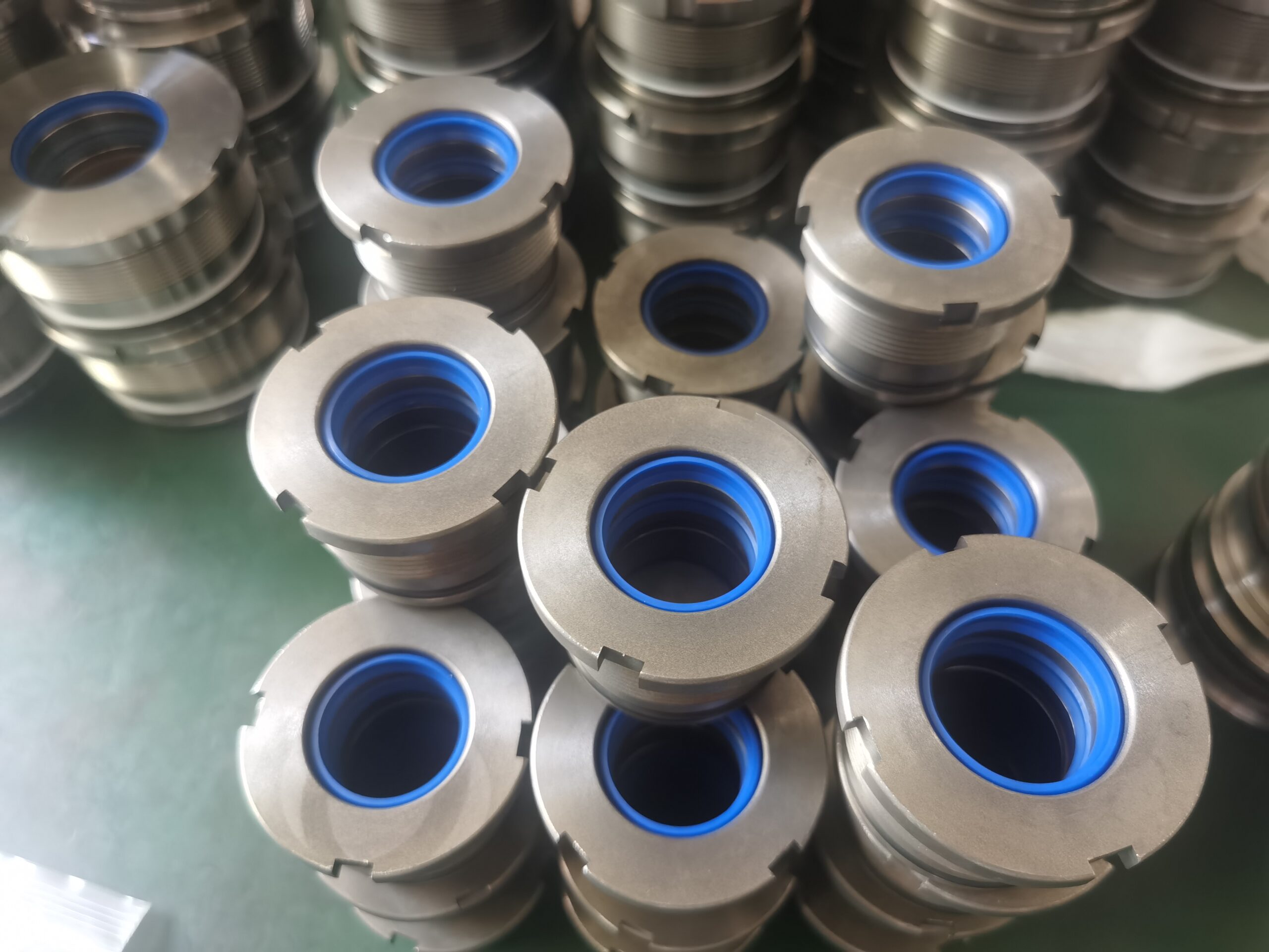
9. Air Remains Trapped in the Cylinder or Hydraulic Circuit
The cylinder does not leak. Nothing appears bent. The pressure looks normal.
But the movement is soft, jerky, noisy, or difficult to control.
What You Notice
- The rod moves in short jumps.
- The cylinder feels spongy under load.
- The system makes unusual knocking or whining sounds.
- The oil foams in the reservoir.
- The cylinder position is unstable.
Why It Happens
Air is compressible. Hydraulic oil is normally treated as nearly incompressible.
When air remains in the cylinder or lines, part of the hydraulic energy compresses the air instead of moving the load smoothly.
Air may enter when the cylinder or hoses are changed, the reservoir oil level is low, a suction connection leaks, or the installed port orientation traps air.
How to Confirm It
Look for foaming oil, unstable motion, delayed response, noise, or changes in movement after several slow cycles.
Also inspect suction hoses, fittings, reservoir level, and any point where air may enter the pump supply.
How to Prevent It
Commission the hydraulic system according to the machine manufacturer’s procedure.
Where controlled bleeding is required, begin at low speed and low load. Keep the reservoir filled correctly and inspect suction connections for air leakage.
Do not repeatedly drive the cylinder at full speed in an attempt to “push the air out.” That can create uncontrolled movement and end-of-stroke impact.
10. Ports, Hoses, or Valves Restrict the Oil Flow
The cylinder has the correct force. It fits the machine. It passes a pressure test.
Yet it moves too slowly, overheats, or behaves differently during extension and retraction.
What You Notice
- The cylinder moves slowly even when pressure is available.
- The rod retracts more slowly than expected.
- Hoses, fittings, or ports become hot.
- The rod seal leaks only during high-speed operation.
- The cylinder cavitates or makes noise.
- The machine behaves normally at low flow but poorly at full pump output.
Why It Happens
Port thread size does not always tell you the true internal flow area.
A small passage, long hose, restrictive fitting, undersized valve, blocked quick coupling, or high return-line pressure can limit oil movement.
On the rod side, the returning oil flow can be higher than the pump flow because the piston displaces oil from the annular area at a different volume ratio.
If the return path is too restrictive, back pressure increases and can load the rod seal in a way that was not expected.
How to Confirm It
Check:
- Pump flow rate;
- Required cylinder speed;
- Port passage size;
- Hose internal diameter and length;
- Fittings and elbows;
- Quick couplings;
- Valve flow capacity;
- Return-line pressure;
- Correct cap-end and rod-end connections.
How to Prevent It
Specify required extension and retraction speed as well as working pressure.
The manufacturer can then review whether the selected ports and internal passages are suitable for the expected flow.
Also confirm port direction and installation clearance. A technically correct port can still create an installation problem when the hose cannot be routed without sharp bends or contact with the machine frame.
Installation Damage Can Ruin a Correctly Manufactured Cylinder
Not every early failure begins during design.
Sometimes the damage happens during the few hours between unpacking and commissioning.
| Installation Mistake | Possible Result | Better Practice |
|---|---|---|
| Using a chain or metal clamp directly on the piston rod | Chrome scratches that cut the rod seal | Lift from approved mounting points and protect the rod surface |
| Hammering a tight mounting pin into place | Preloaded misalignment and damaged bearings | Correct bracket alignment before pin installation |
| Leaving ports open in a dirty workshop | Dust and metal particles enter the cylinder | Keep ports capped until hoses are ready |
| Welding near the assembled cylinder | Seal heat damage, rod contamination, tube distortion | Remove or fully protect the cylinder before welding |
| Overtightening threaded fittings | Cracked ports, damaged sealing faces, distorted fittings | Use the correct sealing method and tightening specification |
| Using the internal piston as the machine stop | Repeated impact on piston, gland, welds, or mounts | Use appropriate cushioning, valve control, or external stops |
| Starting immediately at full speed and full load | Air-related movement, impact, and uncontrolled loading | Commission gradually under controlled conditions |
Is It an Installation Problem or a Manufacturing Defect?
This is usually the first difficult conversation after a new cylinder fails.
The buyer says the cylinder is new. The supplier says it passed pressure testing. The installer says the mounting points were already there.
None of those statements proves the cause.
You need evidence.
| Failure Evidence | More Likely Installation or System Related | More Likely Cylinder Related |
|---|---|---|
| Rod seal leakage | Uneven wear, side load, scratched rod, contamination, high return pressure | Incorrect seal installation, wrong gland dimensions, pre-shipment seal damage |
| Rod bending | Side load, overload, impact, wrong machine geometry | Rod material or diameter does not match the approved design |
| Incorrect installation dimensions | Machine dimensions differ from the information supplied | Manufactured dimensions differ from the approved drawing |
| Weld or mounting failure | Twisting, shock, frame deformation, offset load | Weld defects, incorrect material, or structure outside the approved design |
| Internal bypass | Contaminated oil, pressure spike, incompatible fluid | Damaged piston seal, poor bore finish, incorrect internal clearance |
| Jerky movement | Air, valve instability, poor oil supply, mounting friction | Incorrect internal assembly or excessive seal friction |
A factory pressure test verifies the cylinder under controlled conditions.
It does not recreate worn pins, bent brackets, dirty hoses, machine impact, incorrect valves, or every load angle in the actual equipment.
At the same time, “installation problem” should not become a convenient answer for every failure. The manufactured cylinder must still match the approved drawing, material requirements, dimensions, assembly specifications, and agreed test conditions.
Compare four things:
- The approved drawing;
- The cylinder inspection and test results;
- The actual installed dimensions;
- The real operating pressure, load, fluid, and movement.
That comparison is much more useful than deciding responsibility from a single photograph.
Seven Checks Before Removing the Failed Cylinder
Once the cylinder is removed, you may lose important evidence.
The hoses are disconnected. The pin stress disappears. The bracket returns to its unloaded position. Oil is cleaned away. Nobody remembers exactly when the noise occurred.
Record the installed condition first.
1. Make the Machine Safe
Lower the equipment or support it mechanically. Release stored hydraulic pressure according to the machine procedure.
Do not rely on the failed cylinder or a closed valve to hold the load.
2. Photograph the Complete Installation
Take wide and close photographs showing:
- The complete cylinder;
- Both mounting points;
- Pins and bushings;
- Port positions;
- Hose routing;
- Oil leakage location;
- Nearby brackets and structures.
3. Record When the Failure Happens
Does it happen during extension, retraction, lifting, lowering, holding, direction change, high speed, full load, or end of stroke?
“The cylinder leaks” is useful. “The rod seal leaks only when retracting a full load” is much more useful.
4. Record a Short Operating Video
Where safe, show the complete cylinder and both mounts in the same frame.
A video can reveal twisting, delayed movement, hose movement, frame deflection, noise, and the exact point where the failure appears.
5. Inspect the Rod, Pins, and Mounts
Look for:
- Rod scratches or dents;
- Uneven polished areas;
- Bent pins;
- Oval mounting holes;
- Seized bearings;
- Loose brackets;
- Cracked paint around a moving weld.
6. Measure Pressure During the Failure Condition
A pressure reading with the machine idling may not help.
Where the system design and safety procedure allow, record pressure during the actual movement that causes the problem.
7. Collect the Oil and Damaged Parts
Do not throw away the seals, wear rings, broken mounting pieces, filter element, or contaminated oil sample.
The wear pattern may show whether the failure came from heat, contamination, extrusion, side load, or incorrect assembly.
Failure Evidence Checklist
- ☐ Approved cylinder drawing;
- ☐ Full installation photographs;
- ☐ Operating video;
- ☐ Working and peak pressure readings;
- ☐ Hydraulic oil type and temperature;
- ☐ Date and operating hours when failure occurred;
- ☐ Close-up photographs of damaged parts;
- ☐ Machine model and cylinder function;
- ☐ Previous repair or failure history;
- ☐ Actual mounting and stroke measurements.
Do Not Send Only a Photo of the Oil Leak
A useful failure review combines the drawing, installation, operating pressure, machine movement, and damaged components.
Should You Repair the Cylinder or Order a Corrected Replacement?
Replacing every failed cylinder is expensive.
Repairing every failed cylinder can be even more expensive when the original design or installation is wrong.
| Condition | Repair May Be Suitable | A Corrected Replacement May Be Better |
|---|---|---|
| Rod seal leakage | Rod, gland, tube, and alignment remain within specification | Leakage is repeatedly caused by side load or incorrect seal design |
| Rod damage | Minor surface damage can be restored within dimensional limits | The rod is bent, deeply scored, too small, or repeatedly failing |
| Incorrect dimensions | A replaceable rod end or spacer can be safely corrected | Stroke, closed length, trunnion position, or base mount is wrong |
| Mounting damage | The root cause is known and a qualified repair procedure is available | The mounting structure or load path requires redesign |
| Slow or unstable operation | Valve, hose, or system adjustment solves the problem | Ports, bore, rod, seals, or cushioning are unsuitable |
| Repeated failure | The root cause has been verified and corrected | The same specification has failed more than once without a confirmed solution |
Do not automatically copy a failed cylinder.
The old unit may already have been modified. Its rod may be bent. Its mounting eye may have been repaired. Its internal stop may be broken. The original design may also have been unsuitable for the actual application.
This is one of the same risks discussed in our guide to hydraulic cylinder purchasing mistakes that cause leakage, delays, and additional cost.
What Information Should You Send for a Corrected Custom Cylinder?
You do not need to prepare a perfect engineering report before contacting a manufacturer.
You do need to provide enough information to stop the same problem from being copied.
| Information | What to Send | Why It Matters |
|---|---|---|
| Existing cylinder | Drawing, sample, nameplate, or measured dimensions | Provides the basic replacement geometry |
| Machine application | Machine type, cylinder function, and equipment model | Explains what movement and load the cylinder controls |
| Bore and rod | Bore diameter and piston rod diameter | Determines force, speed, and rod strength |
| Stroke and lengths | Stroke, closed length, and extended length | Confirms installation and machine movement |
| Mounting | Mount type, pin diameter, width, bearing, and position | Controls alignment and force transfer |
| Pressure | Normal pressure, relief setting, and peak pressure | Affects tube, rod, seals, welds, and mounts |
| Load | Maximum load, direction, leverage, and impact | Required for force and buckling review |
| Speed and flow | Required movement speed or pump flow | Determines ports, passages, seals, and cushioning |
| Fluid | Hydraulic oil or other fluid type | Required for seal compatibility |
| Temperature | Ambient and oil temperature range | Affects seals, oil viscosity, and clearances |
| Environment | Dust, mud, salt, moisture, chemicals, or abrasion | Determines wipers, coatings, and corrosion protection |
| Duty cycle | Cycles per hour and operating hours per day | Affects heat, wear, fatigue, and expected life |
| Failure evidence | Photos, video, damaged parts, pressure records, and history | Helps correct the cause instead of copying it |
ZHY also provides a dedicated custom hydraulic cylinder specification and RFQ checklist for buyers preparing a new or replacement enquiry.
How ZHY Reviews a Failed Custom Cylinder Project
A useful replacement review starts with one question:
Why did the previous cylinder fail?
The answer may change the new drawing.
For example:
- A bent rod may require a larger rod, but it may also require corrected alignment.
- A leaking seal may require a different compound, but it may also require lower side load.
- A cracked eye may require stronger steel, but it may also require a revised load path.
- A slow cylinder may require larger ports, but the restriction may actually be in the valve or hose.
- An incorrect stroke may require a revised cylinder, but the original measurement may have been taken from a damaged sample.
For custom and replacement projects, the review can include:
- Drawing and dimension confirmation;
- Bore, rod, and stroke review;
- Closed and extended length confirmation;
- Mounting and pin geometry review;
- Working and peak pressure confirmation;
- Rod buckling considerations;
- Seal selection for the fluid and temperature;
- Port size, thread, direction, and flow review;
- Material and surface-treatment selection;
- Prototype production and pressure testing;
- Inspection records before repeat OEM production.
The cylinder structure also needs to match your maintenance and installation priorities. Our comparison of welded and tie-rod hydraulic cylinders explains how strength, installation space, repair access, and OEM use affect that decision.
Custom Replacement Cylinders Based on the Real Failure Condition
ZHY Hydraulic manufactures custom hydraulic cylinders according to drawings, samples, mounting dimensions, pressure, load, fluid, and operating environment.
For a failed-cylinder project, send the original specification together with installation photographs and failure evidence. Our goal is not simply to copy the old unit. It is to confirm which details should remain and which details may need correction.
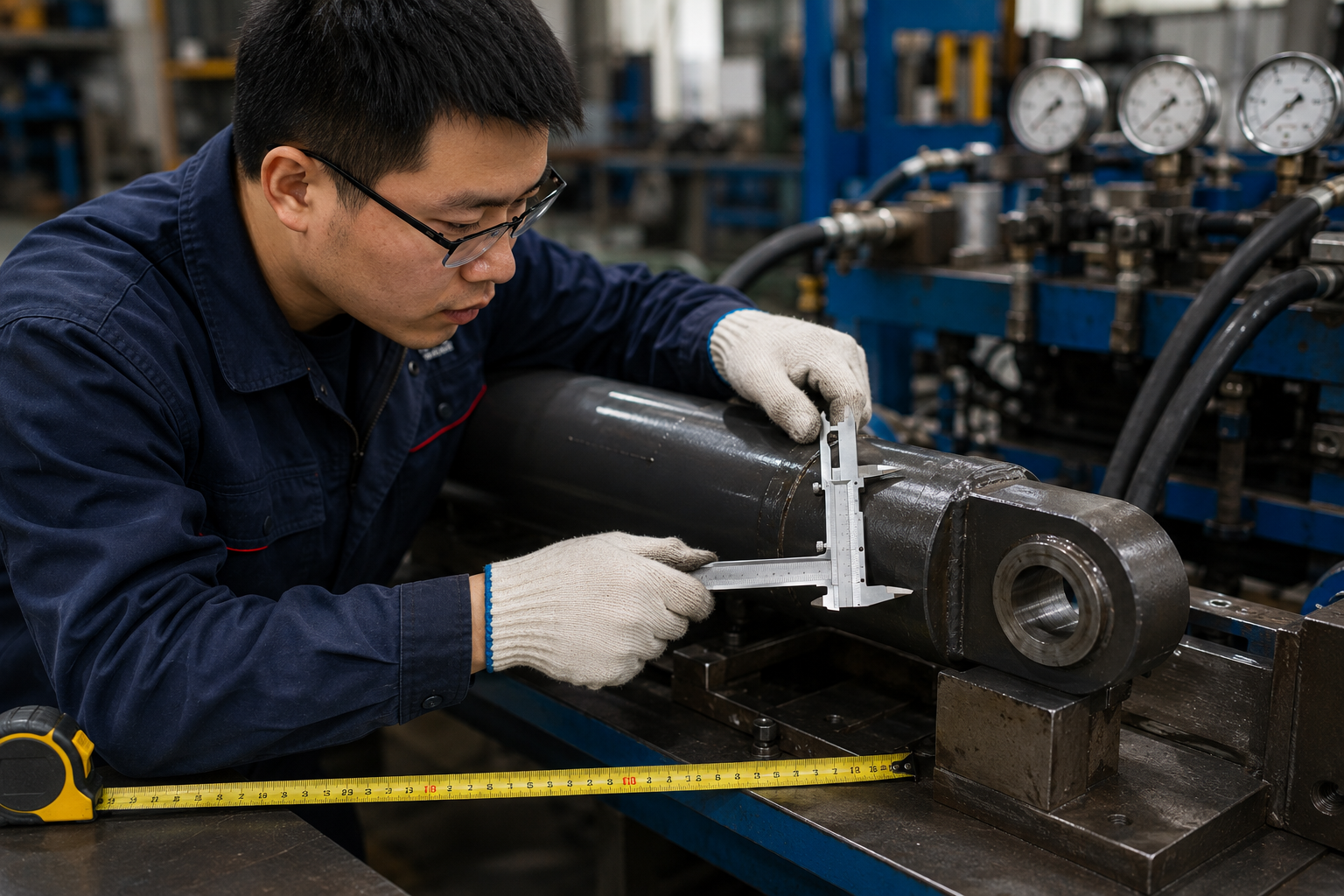
Testing a Corrected Replacement Cylinder
A corrected design should not move directly from drawing approval to a large OEM order.
Where the design, mounting, material, seals, or operating conditions have changed, start with a prototype.
Depending on the project, pre-shipment checks may include:
- Critical dimensional inspection;
- Stroke and mounting-distance verification;
- Rod diameter and surface inspection;
- Port thread, position, and direction confirmation;
- Low-pressure movement testing;
- External leakage testing;
- Internal leakage testing;
- Pressure testing according to the agreed requirement;
- Weld and surface inspection;
- Coating, marking, and packaging checks.
After delivery, prototype testing should also confirm:
- The cylinder installs without forced pin alignment;
- The machine completes the required movement;
- No structure contacts the rod, tube, ports, or hoses;
- The cylinder remains aligned throughout the stroke;
- Speed and control are acceptable;
- The cylinder holds the required load;
- Oil temperature and return pressure remain acceptable;
- No abnormal wear appears after the agreed trial period.
ISO 10100:2020 specifies acceptance and function tests for hydraulic fluid-power cylinders. ISO 4413:2010 covers general rules and safety requirements for hydraulic fluid-power systems and components. Project-specific pressure, test method, acceptance limits, mounting, materials, and documentation still need to be agreed for each application.
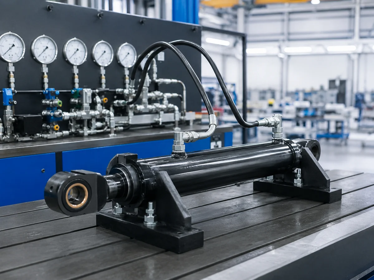
Buyer Checklist Before Installing the Next Cylinder
- ☐ The cylinder matches the approved drawing;
- ☐ Bore, rod diameter, and stroke are confirmed;
- ☐ Closed and extended mounting centers are confirmed;
- ☐ Pin diameters, widths, bearings, and clearances are correct;
- ☐ The cylinder moves freely through the full equipment range;
- ☐ The mounting points remain aligned under load;
- ☐ The piston rod surface has no scratches or impact damage;
- ☐ Ports and hoses are clean before connection;
- ☐ The circuit has been flushed after any destructive previous failure;
- ☐ Filters and hydraulic oil have been inspected;
- ☐ Port thread, direction, and flow capacity are correct;
- ☐ Normal and peak pressures are within the approved limits;
- ☐ The fluid and temperature match the selected seals;
- ☐ The system is commissioned gradually;
- ☐ Prototype performance is confirmed before repeat production.
Frequently Asked Questions
Why is my new hydraulic cylinder leaking after installation?
A new cylinder may leak because of a damaged seal, scratched rod, installation contamination, excessive return pressure, incorrect seal material, mounting misalignment, or side loading. Inspect the installation and hydraulic circuit before replacing the seal.
Is hydraulic cylinder leakage always a manufacturing defect?
No. A manufacturing defect can cause leakage, but contaminated oil, rod damage, poor alignment, side loading, incompatible fluid, pressure spikes, and installation damage can also cause a correctly manufactured cylinder to leak.
Can a hydraulic cylinder fit correctly and still be misaligned?
Yes. Both mounting pins may fit while the cylinder centerline remains incorrect. Alignment can also change as the machine moves or the frame bends under load.
Can side loading damage a new hydraulic cylinder?
Yes. Side loading can cause uneven seal and guide wear, rod scoring, friction, heat, internal damage, and rod bending. Replacing the seal alone will not correct the load.
Why does a hydraulic cylinder move in a jerky way after installation?
Jerky movement may come from trapped air, contaminated oil, poor alignment, insufficient oil supply, excessive seal friction, unstable valve control, or changing machine loads.
Can incorrect mounting bend the piston rod?
Yes. Incorrect mounting can create side load or increase the rod’s unsupported length. Under high compression, this may cause buckling or permanent bending.
Why does the cylinder hold pressure during testing but fail on the machine?
Factory testing checks the cylinder under controlled conditions. The installed cylinder may experience side load, frame movement, contamination, restricted hoses, pressure spikes, impact, or load angles that are not reproduced on the test bench.
Should I repair a bent hydraulic cylinder rod?
A slightly damaged rod may sometimes be restored after professional inspection. A bent, deeply scored, undersized, or repeatedly failing rod usually requires replacement and a review of the load, mounting, and buckling risk.
Can ZHY manufacture a cylinder from an old sample?
Yes. ZHY can manufacture from a sample, drawing, or measured specifications. When the old cylinder has failed, you should also provide machine photos, pressure, load, fluid, and failure evidence so the same problem is not copied.
What should I send for a replacement cylinder review?
Send the drawing or dimensions, machine model, cylinder function, bore, rod, stroke, mounting details, ports, pressure, fluid, temperature, quantity, installation photos, failure photos, and an operating video where available.
Find the Cause Before You Order the Next Cylinder
A replacement cylinder should solve the failure, not repeat it.
Send ZHY Hydraulic your drawing, installation photos, working pressure, machine information, and damaged-part photos. We can review the project for a corrected prototype or OEM replacement.
Final Recommendation
When a hydraulic cylinder fails shortly after installation, do not begin by ordering the same cylinder again.
Begin with the evidence.
Check whether the cylinder is straight throughout the complete stroke. Inspect the pins, bushings, rod, seals, oil, hoses, ports, valves, and mounting structure. Compare the installed cylinder with the approved drawing. Measure pressure during the actual failure condition.
If the cylinder does not match the approved specification, document the difference.
If the cylinder matches the drawing but the machine creates side load, pressure spikes, contamination, or incorrect movement, correct the application before installing another unit.
If the original specification was incomplete, update the drawing and technical requirements before replacement production.
The best custom cylinder is not simply the one that fits between two pins. It is the one that matches your real load, pressure, movement, fluid, mounting geometry, environment, and maintenance requirements.
Technical Review and EEAT Information
Author: Lulu, Hydraulic Cylinder Technical Content Specialist at ZHY Hydraulic
Technical review: Reviewed by Senior Hydraulic Engineer
Manufacturing experience: This guide reflects practical experience from custom cylinder drawing confirmation, machining, welding, assembly, seal selection, dimensional inspection, pressure testing, and replacement-project review.
Applicable references: ISO 10100:2020 for hydraulic cylinder acceptance and function tests, and ISO 4413:2010 for general hydraulic-system safety requirements.
Project-specific confirmation: Bore, rod diameter, stroke, mounting geometry, working pressure, peak pressure, buckling safety, seals, fluid, temperature, port flow, surface treatment, testing pressure, and acceptance criteria must be confirmed for each project.
Image statement: Original ZHY factory and inspection photographs should be used whenever available. Generated explanatory images must not be presented as actual customer projects or factory test records.
Technical Sources
ISO 10100:2020 — Hydraulic fluid power — Cylinders — Acceptance and function tests
ISO 4413:2010 — Hydraulic fluid power — General rules and safety requirements for systems and their components
- ZHY Hydraulic custom cylinder manufacturing, inspection, pressure-testing, and OEM replacement project experience.