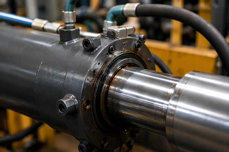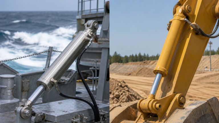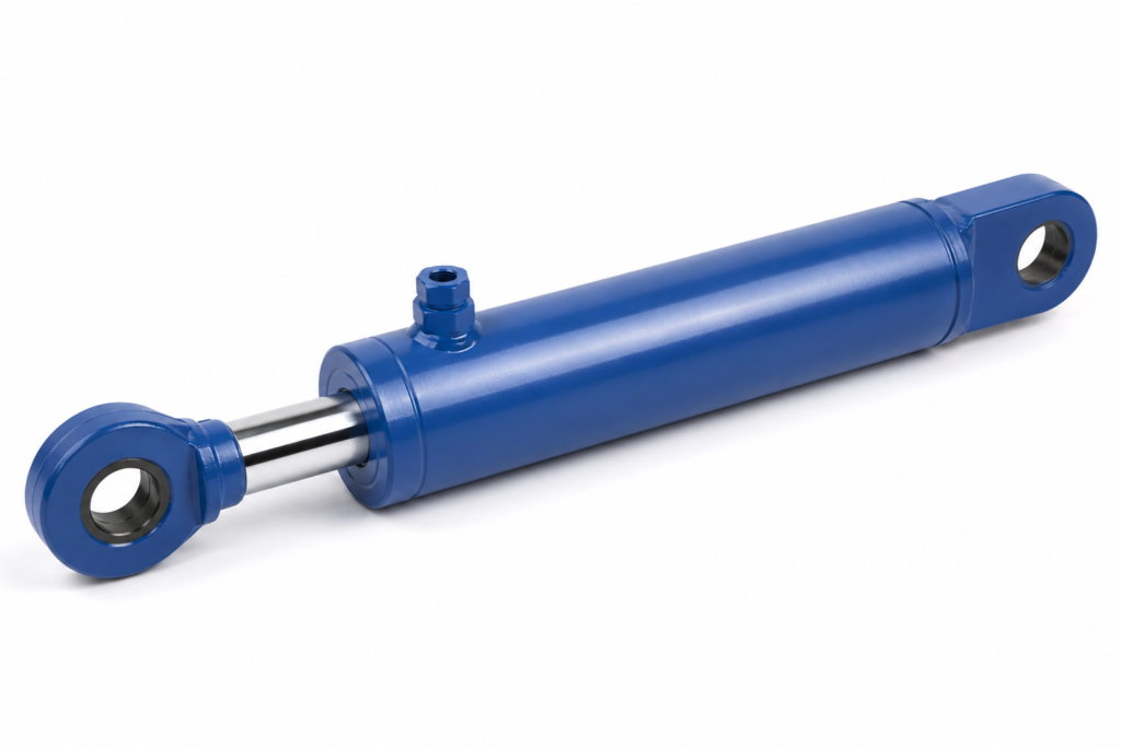
Why is the cylinder moving slower than expected?
A hydraulic cylinder is usually slow because the actuator is not receiving enough usable flow at its ports, not because the cylinder is automatically the wrong size. For procurement managers and engineering buyers, the first check should be pump delivery, port restriction, hose routing, and valve metering before replacing the cylinder.
In real equipment projects, the common mistake is to order a larger or smaller cylinder when the machine misses cycle time. A larger bore increases force, but it also increases oil volume per millimeter of stroke. If the pump flow stays unchanged, the larger bore can make the extension slower. A smaller bore may move faster, but it may fail the force requirement or raise operating pressure beyond the intended design margin.
This article is written for engineering buyers, maintenance managers, and OEM procurement teams that need a practical calculation path before placing a batch order. The main scenario is mobile and industrial hydraulic equipment where a cylinder must hit a defined extension or retraction time under load, such as lifting arms, presses, clamps, dump mechanisms, and test fixtures.
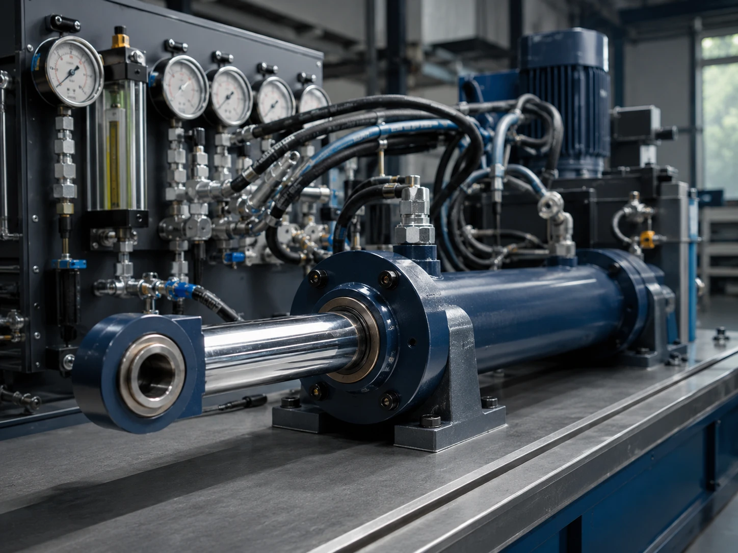
The strongest rule is simple: calculate the required flow for the target speed, then verify that the power unit, valve, port, and hose path can deliver it without excessive pressure loss. ZHY often asks buyers for stroke, target cycle time, pump flow, working pressure, port size, and mounting orientation before recommending a cylinder change, because speed is a system result rather than a cylinder-only specification.
What formula is used to calculate hydraulic cylinder speed?
The direct formula is speed equals flow divided by effective area. Extension speed uses the full piston area, while retraction speed uses the annular area after subtracting the rod area. This is the core of how to calculate hydraulic cylinder speed for both single-machine troubleshooting and OEM cylinder selection.
Use the same unit system throughout. In metric work, convert flow to cubic millimeters per second and area to square millimeters, then the result is millimeters per second. In inch-based work, convert gallons per minute to cubic inches per minute, divide by square inches, and then convert inches per minute to inches per second if needed.
- Piston area
- The full bore area that receives oil during extension. It is calculated from bore diameter and determines extension speed and push force.
- Annular area
- The effective rod-side area during retraction. It equals piston area minus rod area, so retraction is often faster than extension at the same flow.
- Flow rate
- The oil volume delivered per unit time, commonly shown as L/min or gpm. Flow primarily controls speed, while pressure primarily relates to force.
- Pressure drop
- The pressure lost through valves, ports, fittings, and hoses. High pressure drop can reduce usable speed and create heat.
For example, a 100 mm bore cylinder has a piston area of about 7,854 mm². If the pump delivers 30 L/min to the cap end, that is 500,000 mm³/s. Dividing flow by area gives about 63.7 mm/s extension speed before losses. If the cylinder has a 50 mm rod, the annular area is about 5,891 mm², so the same flow gives about 84.9 mm/s retraction speed.
These numbers are theoretical. Real speed can be lower because directional valves, quick couplers, elbows, undersized ports, long hoses, contamination, and load-induced pressure all affect delivered flow. Use the formula as the first diagnostic filter, then measure actual flow and pressure near the cylinder if the calculated value and field value are far apart.
Key Takeaways
- Cylinder speed is governed first by oil flow divided by effective piston or annular area.
- Extension and retraction speeds differ because the rod reduces the working area on the rod side.
- If speed is too slow, check pump flow, valve capacity, port size, and hose limits before changing bore size.
- Higher speed can increase pressure drop, heat, shock, seal wear, and stopping distance.
- ISO 4413 requires hydraulic systems to be designed with safe control of pressure, motion, and energy release.
How do bore, rod, flow, and stroke change cycle time?
Cycle time is determined by the volume required to move the piston through the stroke and the real flow available to fill or exhaust that volume. Bore and stroke set the oil volume; rod diameter changes the retraction volume; pump and valve capacity decide whether the target time is realistic.
A buyer who wants to speed up hydraulic cylinder movement should not only ask for a smaller cylinder. The decision must compare force, buckling margin, seal life, port velocity, and machine stability. A press cylinder may tolerate slower travel if it needs high force and smooth control, while a clamp cylinder may justify higher speed if the stroke is short and the load is predictable.
| Parameter change | Speed effect | Force or system effect | Best engineering use |
|---|---|---|---|
| Increase pump flow | Usually increases speed if valves, ports, and hoses can pass the flow | May increase heat and pressure drop if the circuit is restricted | Choose when force is correct but cycle time is too long |
| Increase bore size | Slows speed at the same flow because piston area is larger | Increases push force at the same pressure | Choose when force is insufficient and slower motion is acceptable |
| Decrease bore size | Increases speed at the same flow | Reduces available force and may require higher pressure | Choose only after confirming load force margin |
| Increase rod diameter | Can increase retraction speed because annular area becomes smaller | Improves column strength but reduces pull force | Choose for long-stroke stability and faster return where pull force is not critical |
| Increase port or hose size | May restore lost speed by reducing restriction | Reduces pressure drop and heat generation | Choose when measured pressure drop is high across fittings or hoses |
How to use this table: start with the speed effect column when cycle time is the priority, then check the force or system effect column before approving a design change; if two options look similar, choose the one that fixes the restriction without reducing force margin.
How can you control hydraulic cylinder speed without creating new problems?
The best way to control speed is to meter flow in a stable, load-aware manner while keeping pressure drop, heat, and shock within acceptable limits. Use fixed or adjustable flow controls for simple circuits, pressure-compensated flow controls where load varies, and proportional valves where programmable motion profiles are required.
For simple equipment, a needle valve or throttle valve may be enough to slow down hydraulic cylinder movement. The risk is that a basic throttle does not fully compensate for changing load or oil viscosity. When a heavy load overruns, meter-out control is often safer than meter-in because it restricts the exhaust flow and helps prevent uncontrolled motion.
For production machinery, pressure-compensated valves are more stable because they maintain a set flow over a pressure range. Proportional directional valves add electronic control and can ramp acceleration or deceleration, which reduces shock at the end of stroke. Servo valves offer tighter dynamic control, but they require cleaner oil, stronger commissioning discipline, and higher maintenance capability.
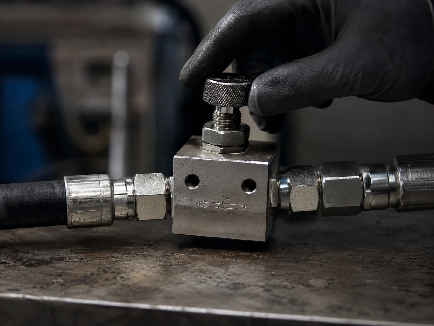
Port size and hose limits matter because flow control does not create flow; it only manages it. Common hydraulic design guidance from hose and fluid power manufacturers uses conservative oil velocity ranges: suction lines are kept low, return lines moderate, and pressure lines higher but still controlled to limit noise, pressure loss, and heat. If a buyer asks how to control hydraulic cylinder speed on a field machine, the practical answer is to identify whether the problem is under-supply, over-speed, or unstable load response.
What should you check before changing the cylinder?
Before changing the cylinder, confirm whether the existing actuator is receiving the calculated flow under working load. Measure pressure before and after major restrictions, verify actual pump output, inspect port and hose sizes, and compare no-load speed with loaded speed. This avoids expensive redesign based on the wrong symptom.
A practical diagnostic sequence starts at the power unit. Check pump displacement, rated speed, relief valve setting, oil temperature, filter condition, and directional valve capacity. A worn pump may deliver acceptable flow without load but lose volume under pressure because of internal leakage. A partly clogged filter or quick coupler can also make a correctly sized cylinder appear too slow.
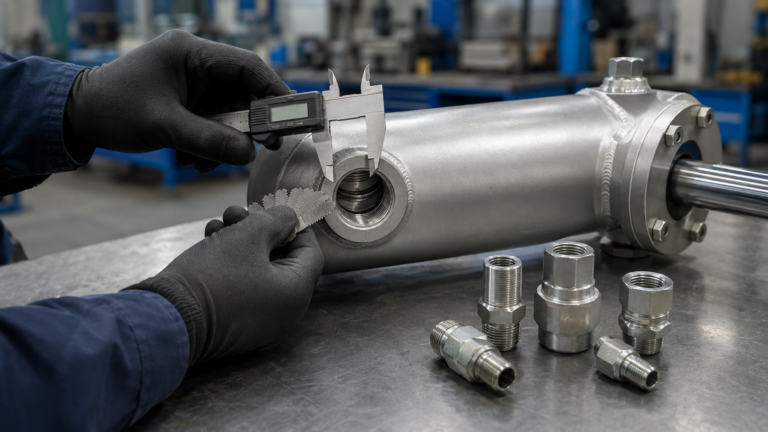
Next, inspect the cylinder path. Undersized SAE or metric ports, too many elbows, long small-bore hoses, and restrictive counterbalance valves can all reduce real flow. If the extend stroke is slow but retract is normal, compare cap-end restrictions with rod-end return restrictions. If both directions are slow, the issue is more likely pump flow, valve spool selection, relief setting, or system heat.
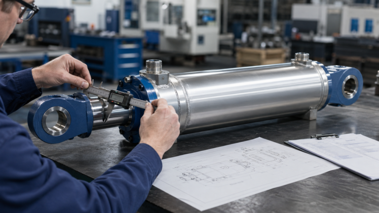
Finally, consider internal leakage. A cylinder with damaged piston seals may fail to hold load or may drift, but internal leakage does not always show as an obvious external oil leak. For acceptance testing, engineering buyers should request pressure holding checks, dimensional inspection, surface finish records for the rod, and seal material confirmation matched to oil type and temperature.
Which speed-control option should you choose?
Choose a control method based on load behavior, accuracy requirement, duty cycle, and maintenance skill. Fixed restrictors suit repeatable low-cost motion, adjustable flow controls suit commissioning flexibility, pressure-compensated valves suit changing loads, and proportional control suits machines that need controlled acceleration and electronic repeatability.
| Situation | Recommended option | Reason | Procurement warning |
|---|---|---|---|
| Cylinder is too slow in both directions | Check pump flow, relief setting, and valve flow rating | The whole circuit may be flow-limited | Do not reduce bore until required force is recalculated |
| Cylinder extends too fast under gravity load | Use meter-out control or a counterbalance valve | Exhaust control helps prevent runaway motion | Confirm load-holding function and thermal effect |
| Speed changes when load changes | Use pressure-compensated flow control | It keeps flow more stable across pressure variation | Specify adjustment range and rated flow clearly |
| Machine needs smooth acceleration | Use proportional directional control | Electronic ramping reduces shock and improves repeatability | Require contamination control and commissioning support |
| Cylinder is correct but ports are restrictive | Increase port, fitting, or hose capacity | Lower restriction can recover speed without changing force | Check envelope space and hose bend radius |
How to use this table: match the observed symptom in the first column, then use the warning column as the final approval gate; when two recommendations are close, select the one that preserves force and safety while reducing restriction.
What trends are changing hydraulic cylinder speed requirements?
Speed requirements are becoming more measurable, more energy-aware, and more connected to electronic control. OEM buyers increasingly ask for predictable cycle time, smoother motion, lower heat generation, and sensor-ready cylinders rather than only bore, stroke, and pressure ratings.
Electrified and hybrid machines are pushing hydraulic systems to waste less energy through throttling. A circuit that controls speed by dumping excess flow across a restriction may be simple, but it creates heat and can require larger cooling capacity. Load-sensing pumps, variable-displacement pumps, and electrohydraulic valves are therefore becoming more attractive in machines with variable duty cycles.
Condition monitoring also changes purchasing logic. Position sensors, pressure transducers, and flow measurement allow maintenance teams to compare expected speed against actual speed over time. When a cylinder slowly loses speed, the data can show whether the issue is leakage, pump wear, contamination, or valve drift. This helps buyers justify better sealing systems, improved filtration, or factory testing documentation from suppliers such as ZHY.
Regulatory and safety expectations remain central. ISO 4413:2010 sets general rules and safety requirements for hydraulic fluid power systems, including safe control of motion and prevention of hazards from pressure. In the United States, OSHA 29 CFR 1910.147 governs control of hazardous energy during servicing and maintenance. These sources do not tell buyers a target cylinder speed, but they shape how speed must be controlled, stopped, locked out, and verified.
Practical Asset: Speed Calculation and Control Checklist
Use this checklist before asking a supplier to resize a hydraulic cylinder. It is designed for engineering buyers who need a repeatable way to separate cylinder sizing problems from system-flow problems.
- Define the motion target. Record stroke length, required extend time, required retract time, load direction, duty cycle, and whether the motion must stop softly or only reach the end position.
- Calculate theoretical speed. Use piston area for extension and annular area for retraction. Compare calculated speed with the target speed before ordering any new cylinder.
- Verify available pump flow. Ask for pump displacement, drive speed, measured flow at working pressure, relief valve setting, and oil temperature during the test.
- Check valve capacity. Request the directional valve model, rated flow, spool type, pressure drop curve, and whether the circuit uses meter-in, meter-out, or pressure-compensated control.
- Inspect ports, fittings, and hoses. Confirm port thread, internal passage size, hose inside diameter, hose length, bend radius, quick couplers, elbows, and return-line restriction.
- Measure pressure drop. Install pressure gauges or sensors before and after suspected restrictions. High differential pressure across a small component is a strong sign that speed is being lost there.
- Separate no-load and loaded behavior. If no-load speed is normal but loaded speed is poor, investigate pump wear, relief setting, pressure compensation, internal leakage, and load-induced valve behavior.
- Confirm safety controls. Check load-holding valves, emergency stop behavior, end-of-stroke cushioning, lockout procedure, and whether motion can run away under gravity.
- Send complete data to the supplier. Share bore, rod, stroke, mounting, working pressure, flow data, port size, oil type, temperature range, and target cycle time so the recommendation is based on the whole system.
FAQ
1. What is the formula for hydraulic cylinder speed?
Hydraulic cylinder speed is calculated by dividing oil flow rate by the effective piston area. Extension speed uses the full bore area, while retraction speed uses the annular area after subtracting the rod area. Real speed may be lower because of valve pressure drop, hose restriction, port size, oil temperature, and load resistance.
2. Why is hydraulic cylinder retraction often faster than extension?
Retraction is often faster because the piston rod reduces the effective oil area on the rod side. With the same pump flow, a smaller annular area fills or empties faster than the full piston area. However, retract force is lower, so buyers must check both speed and force before approving the cylinder design.
3. How can I speed up a hydraulic cylinder?
You can speed up a hydraulic cylinder by increasing usable pump flow, reducing valve or hose restrictions, increasing port capacity, or selecting a smaller bore only after confirming force margin. Reducing bore size may improve speed, but it can also reduce lifting or pushing force and raise required pressure.
4. How can I slow down a hydraulic cylinder safely?
You can slow down a hydraulic cylinder by using flow control valves, meter-out control, pressure-compensated flow controls, or proportional valves depending on the load behavior. For gravity loads, meter-out or counterbalance control is often safer because it helps prevent runaway movement and uncontrolled descent.
5. What information should I send a supplier for cylinder speed review?
Send bore, rod diameter, stroke, target extend time, target retract time, pump flow, working pressure, valve model, port size, hose size, oil type, temperature range, and load direction. This allows the supplier to check whether the speed issue comes from cylinder sizing, pump flow, valve restriction, hose capacity, or system design.