Why does a hydraulic cylinder matter inside the whole system?
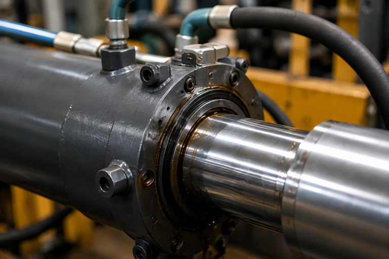
A hydraulic cylinder matters because it is the point where hydraulic energy becomes useful mechanical work. In mobile equipment, the operator may move a lever, but the cylinder is what raises the loader arm, tilts the bucket, clamps a work tool, or holds a suspended load against gravity.
A procurement mistake often begins when the cylinder is treated as an isolated steel component. The real performance comes from the combination of pump displacement, relief pressure, valve metering, hose diameter, port size, seal friction, rod diameter, mounting geometry, and duty cycle. If those parts do not match, a cylinder that looks correct on a drawing can still move too slowly, overheat the oil, drift under load, or buckle the rod.
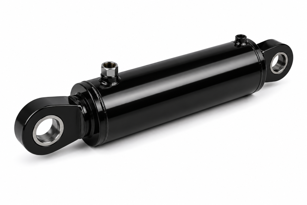
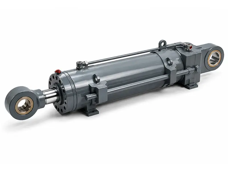
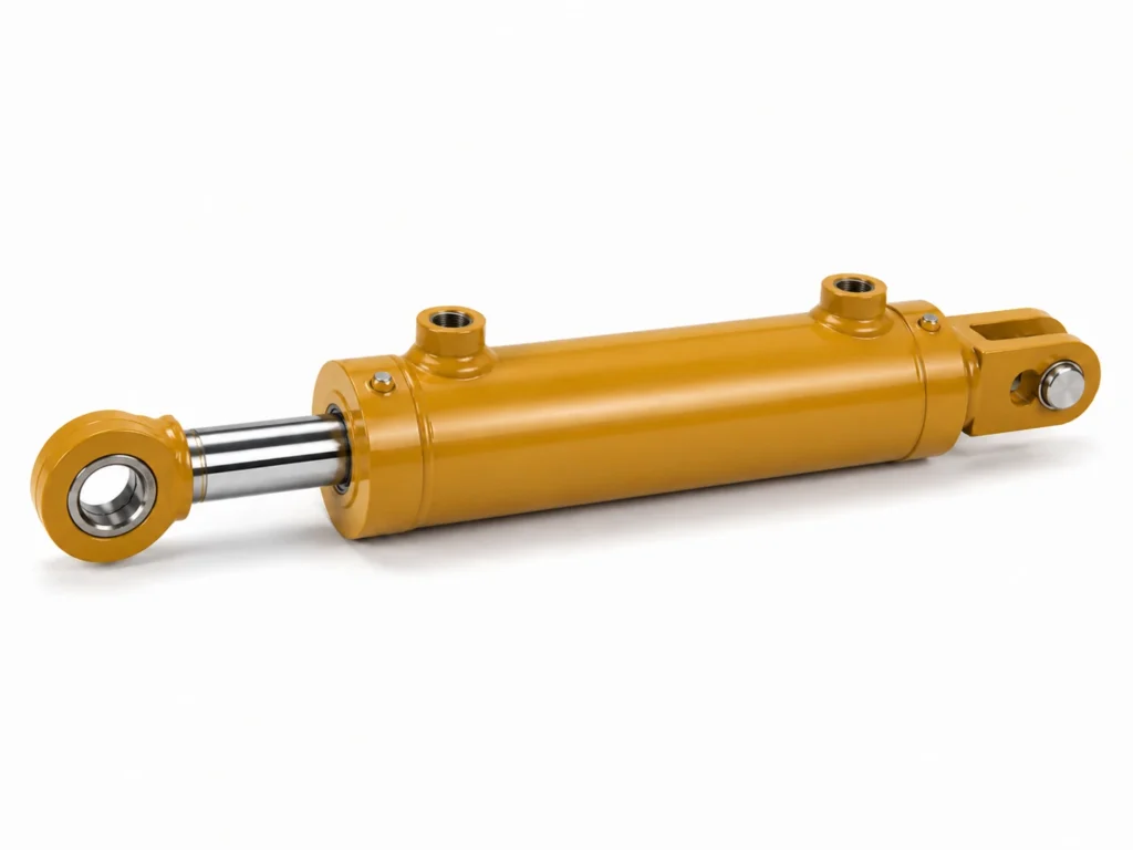
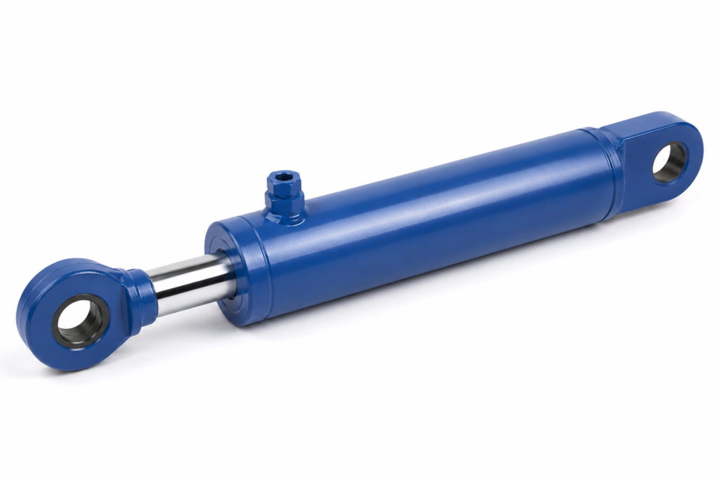
The practical definition is simple: the cylinder receives pressurized oil on one side of a piston and produces controlled linear force through the rod. In a double-acting cylinder, oil can drive both extension and retraction. In a single-acting cylinder, hydraulic pressure usually moves in one direction while gravity, a spring, or the load returns it.
For a project contractor or mobile equipment engineering buyer, this means cylinder selection should start with the machine action, not with the catalog size. A lifting boom, steering axle, compactor blade, and outrigger leg may all use cylinders, but each demands a different balance of thrust, speed, holding stability, shock tolerance, mounting rigidity, and contamination resistance.
What is the hydraulic actuator function in mobile equipment?
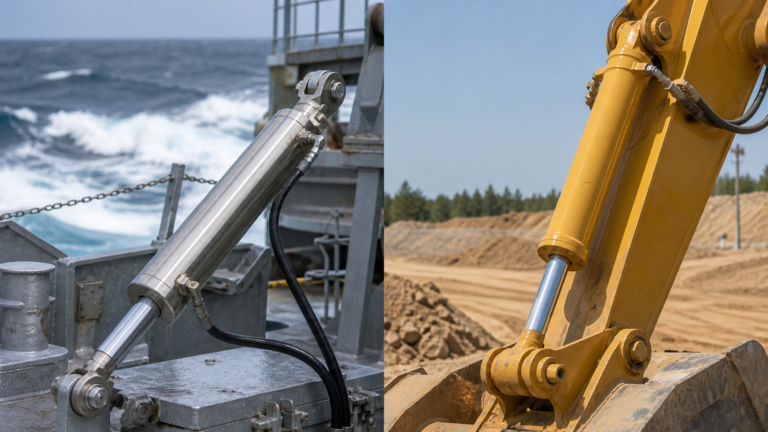
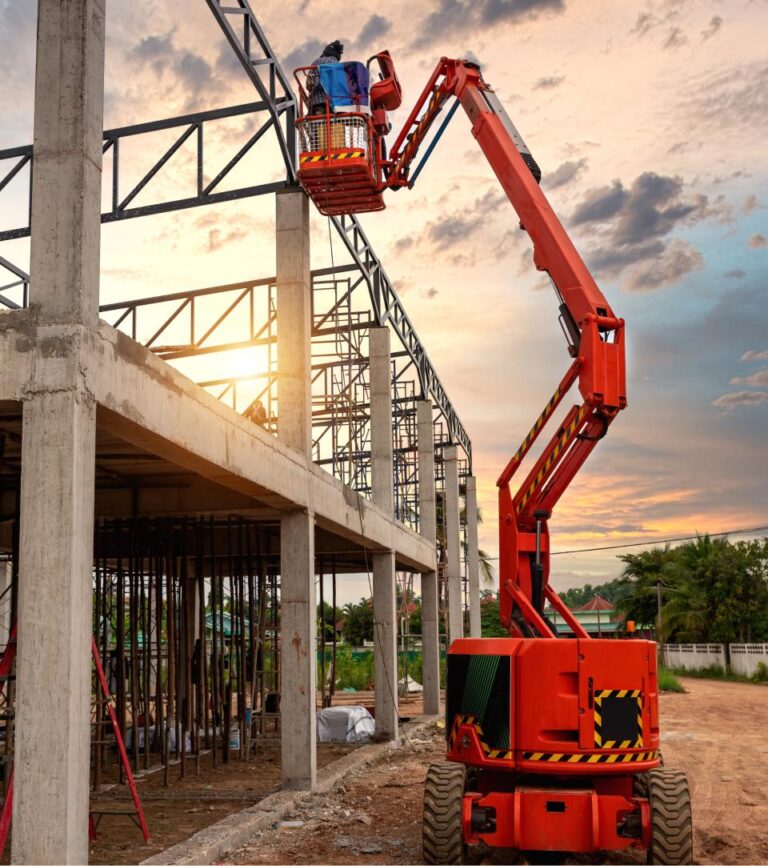
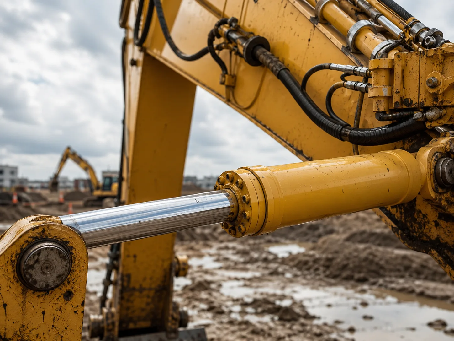
The hydraulic actuator’s function is to turn pressure and flow into predictable motion. Pressure creates force; flow creates speed; valve control determines direction, holding, cushioning, and response. In excavators, loaders, dump trucks, agricultural machines, and access platforms, this function allows compact components to move heavy loads in dirty, high-shock environments.
A cylinder is not selected only because it can generate a high theoretical force. It must generate that force at the right point in the machine linkage and keep doing so through temperature changes, pressure spikes, side loading, vibration, and repeated cycles. ISO 4413 requires hydraulic systems to address safety, component ratings, pressure control, and unintended movement, which is why system-level thinking is not optional in machinery design.
In real projects, the same bore and stroke can behave differently depending on the circuit. A 100 mm bore cylinder at 16 MPa has a theoretical extension force of about 126 kN before friction and efficiency losses. At 25 MPa, the same bore produces about 196 kN. That large change comes from system pressure, not from changing the external size of the cylinder.
Key Takeaways
- The cylinder converts oil pressure into straight-line mechanical work, while pump flow controls movement speed.
- ISO 6020 and ISO 6022 cylinder series commonly reference 16 MPa and 25 MPa mounting families for industrial hydraulic cylinders.
- A cylinder cannot be judged alone because valves, hoses, relief settings, and load geometry decide actual machine behavior.
- Mobile equipment cylinders need attention to shock loads, contamination, rod protection, pin alignment, and holding safety.
- Before ZHY starts cylinder production, engineering buyers should confirm pressure, stroke, mounting, valve type, and duty cycle.
Which cylinder type should you choose for lifting, holding, or pushing?
Choose the cylinder type by matching motion direction, load holding requirement, installation space, and side-load risk. A single-acting cylinder is efficient for one-way lifting or tipping; a double-acting cylinder is the standard choice for controlled movement in both directions; a telescopic cylinder fits long stroke needs where closed length is limited.
| Situation | Recommended cylinder approach | Reason | System check before ordering |
|---|---|---|---|
| Dump body lifting | Single-acting or telescopic cylinder | Gravity can return the body, and long stroke may be required in limited space. | Check relief pressure, tipping angle, mounting pins, and oil volume demand. |
| Loader boom control | Double-acting welded cylinder | Both extension and retraction need positive control under dynamic load. | Check valve metering, hose size, rod buckling, and shock-load protection. |
| Outrigger stabilization | Double-acting cylinder with load-holding valve | Holding safety is as important as lifting force. | Check pilot-operated check valve, ground load, and unintended movement protection. |
| Pressing or clamping | Tie-rod or mill-type cylinder where alignment is controlled | Repeatable force and serviceability are often priorities. | Check bore, cycle rate, seal material, and pressure dwell time. |
How to use this table: read the first column as the machine task, then use the recommended approach only after checking the final column. When two choices look close, prioritize holding safety for suspended loads and prioritize compact closed length for tipping or elevating mechanisms.
The key selection logic is direct. If the system needs one-way lift and gravity return, a single-acting cylinder usually gives the simplest circuit. If the system needs controlled push and pull, choose double-acting. If the stroke is much longer than the available mounting length, use telescopic construction but inspect stability, side loading, and seal access more carefully.
Which parameters control force, speed, and service life?
The most important parameters are bore, rod diameter, stroke, pressure rating, flow rate, mounting style, seal material, tube finish, rod coating, and port size. These values determine force output, retract force, speed, buckling resistance, leakage risk, and long-term maintenance cost.
- Bore diameter
- The internal piston diameter; larger bore creates more extension force at the same pressure.
- Rod diameter
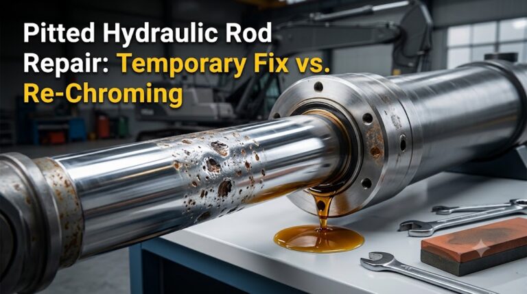
- The chrome-plated moving shaft; larger rods improve buckling resistance but reduce retract-side effective area.
- Stroke
- The usable travel distance; it must match machine geometry and avoid end-of-stroke impact.
- Pressure rating
- The maximum intended working pressure; ISO 6020-1 references a 16 MPa mounting series, while ISO 6022 covers a 25 MPa series.
- Cushioning
- A feature that slows the piston near stroke end to reduce impact in repeated high-speed movement.
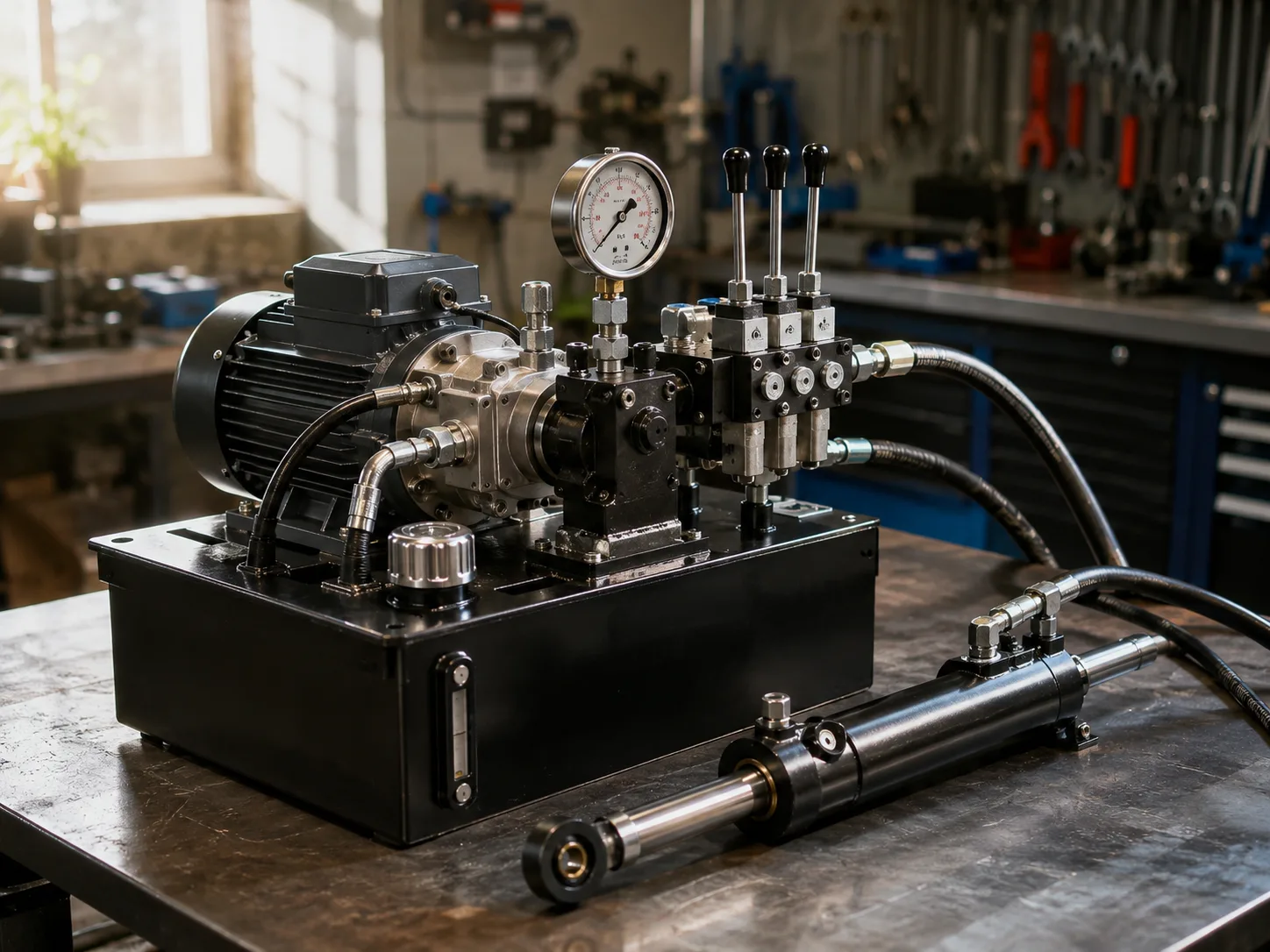
Force is calculated from pressure multiplied by piston area. For example, a 100 mm bore cylinder has a piston area of about 0.00785 square meters. At 16 MPa, theoretical extension force is about 125.7 kN; at 25 MPa, it is about 196.3 kN. Actual usable force is lower after friction, seal drag, pressure losses, and mechanical geometry.
Speed is controlled by flow. A large cylinder connected to a small pump may lift strongly but slowly. A fast cylinder with undersized hoses can create pressure drop, heat, noise, and unstable movement. This is why the hydraulic cylinder system must be sized as a circuit rather than as separate parts.
What happens when the pump, valve, hose, and cylinder do not match?
Mismatch creates performance failures that are often blamed on the cylinder after installation. The common symptoms are slow movement, overheating, rod chatter, internal leakage, seal extrusion, load drift, hose vibration, and poor operator control. The root cause may be an undersized pump, wrong spool type, excessive back pressure, or unverified load-holding circuit.
| Observed problem | Likely system cause | Inspection priority | Procurement consequence |
|---|---|---|---|
| Cylinder moves too slowly | Pump flow or port size is too small for the required speed. | Measure flow rate, hose ID, port type, and valve Cv. | Machine cycle time misses the project target. |
| Load drifts after stopping | Internal leakage, wrong valve spool, or missing load-holding valve. | Perform pressure decay test and valve leakage check. | Safety risk increases for lifting and access equipment. |
| Seals fail early | Pressure spikes, contamination, overheating, or rod misalignment. | Check filtration, oil temperature, rod straightness, and side load. | Warranty claims and downtime become more likely. |
| Rod bends or gland wears | Side loading, long unsupported stroke, or poor mounting alignment. | Review pin centers, rod diameter, guide support, and linkage arc. | Replacement cylinders repeat the same failure. |
How to use this table: start from the observed problem, then inspect the system cause before changing cylinder dimensions. When both cylinder and circuit issues are possible, first verify pressure, flow, oil temperature, and valve leakage because those checks prevent unnecessary redesign.
The most expensive error is ordering a stronger cylinder without confirming the valve and relief setting. A higher-rated cylinder cannot create more useful force if the pump and pressure relief are unchanged. It may also shift the weak point to the hose, mounting bracket, or machine frame.
How do standards and market trends affect cylinder sourcing?
Standards and market trends affect sourcing because hydraulic cylinders are safety-related machine components, not generic metal parts. ISO 4413 sets general safety rules for hydraulic fluid power systems, including pressure control, component rating, leakage, and unintended movement. ISO 5598 standardizes fluid power vocabulary, which helps buyers and suppliers avoid ambiguous terms in drawings and contracts.
For dimensional families, ISO 6020-1 defines mounting dimensions for 16 MPa single-rod cylinders, while ISO 6022 covers 25 MPa single-rod cylinders. These standards do not replace engineering validation, but they help contractors, distributors, and OEM buyers compare mounting interfaces and replacement options more consistently.
The market is also moving toward higher efficiency, integrated sensors, better sealing, and electrification-ready hydraulic architectures. MarketsandMarkets reported the hydraulic cylinder market at about USD 14.3 billion in 2022 with a forecast of USD 18.3 billion by 2027. Fortune Business Insights separately estimated the market at USD 15.32 billion in 2022 and forecast USD 22.21 billion by 2030. The figures differ because of scope and methodology, but both show steady demand from construction, agriculture, material handling, and industrial equipment.
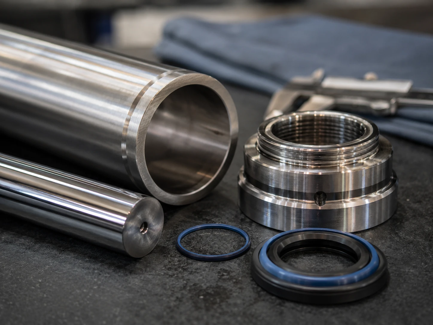
For ZHY customers, the sourcing implication is clear: drawings should include both mechanical dimensions and circuit assumptions. A cylinder made to the correct bore and stroke can still be wrong if the buyer did not specify working pressure, test pressure, seal compound, rod coating, port orientation, or holding valve needs.
Practical Asset: pre-production checklist for hydraulic cylinder orders
Use this checklist before approving samples or batch production. It is designed for engineering buyers, equipment builders, and procurement managers who need to prevent pump, valve, hose, and cylinder mismatch before money is locked into tooling, machining, welding, coating, and packing.
- Ask what exact machine action the cylinder performs: lifting, holding, steering, tipping, clamping, stabilizing, pressing, or positioning.
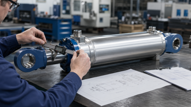
- Request the maximum load, load direction, linkage geometry, pin-center distance, stroke angle, and any side-load condition.
- Confirm system working pressure, relief pressure, expected pressure spikes, and required test pressure before bore size is finalized.
- Check pump flow and target cycle time; then verify whether port size, hose ID, and valve flow capacity can support the required speed.
- Specify single-acting, double-acting, or telescopic construction based on motion direction and available closed length.
- Request rod diameter verification for buckling risk, especially on long-stroke push applications and boom cylinders.
- Define seal material according to oil type, temperature range, contamination level, and duty cycle instead of accepting a generic seal kit.
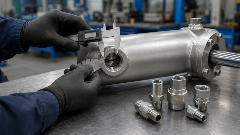
- Confirm mounting style, pin diameter, bearing type, grease access, port orientation, and installation clearance on the real machine.
- Require factory pressure testing, leakage inspection, dimensional report, welding visual check, rod surface inspection, and packaging protection.
- Before ZHY production approval, send the final hydraulic schematic or valve-control description so the cylinder design matches the circuit.
FAQ
1. What is the main function of a hydraulic cylinder?
The main function of hydraulic cylinder is to convert pressurized hydraulic oil into straight-line mechanical force and motion. In equipment, that motion may lift a boom, push a blade, clamp a workpiece, tilt a bucket, or stabilize an outrigger. Pressure determines available force, while pump flow determines speed. The cylinder must also hold loads safely when the valve is centered or when the machine stops.
2. Is a hydraulic cylinder the same as a hydraulic actuator?
A hydraulic cylinder is one type of hydraulic actuator.The broader term actuator includes devices that convert hydraulic energy into motion, including cylinders for linear movement and hydraulic motors for rotary movement. When buyers discuss hydraulic actuator function in mobile equipment, they usually mean how the actuator produces useful machine movement from pressure, flow, and valve control. When buyers discuss hydraulic actuator function in mobile equipment, they usually mean how the actuator produces useful machine movement from pressure, flow, and valve control.
3. How does pressure affect hydraulic cylinder force?
Pressure affects force directly because cylinder force equals pressure multiplied by piston area. A larger bore creates more area, and higher pressure increases output force. For example, a 100 mm bore cylinder produces about 126 kN at 16 MPa before losses and about 196 kN at 25 MPa before losses. Actual working force is lower after friction, pressure drop, seal drag, and mechanical leverage are considered.
4. Why can a correct-size cylinder still fail in a machine?
A correct-size cylinder can fail if the surrounding hydraulic circuit or machine structure is wrong. Common causes include side loading, poor pin alignment, contaminated oil, overheated oil, pressure spikes, undersized hoses, unsuitable valve spools, and missing load-holding valves. This is why the cylinder drawing should be reviewed together with the hydraulic schematic, pressure settings, flow rate, mounting geometry, and duty cycle.
5. What should buyers confirm before ordering hydraulic cylinders?
Buyers should confirm bore, rod diameter, stroke, mounting style, working pressure, test pressure, port orientation, seal material, rod coating, valve control, pump flow, and load-holding requirements. For mobile equipment, they should also check shock loads, contamination exposure, vibration, installation clearance, and packaging protection. The safest workflow is to approve the circuit conditions before cylinder manufacturing begins.
References
- ISO 4413:2010 Hydraulic fluid power — General rules and safety requirements for systems and their components, International Organization for Standardization, ISO, 2010.
- ISO 5598:2020 Fluid power systems and components — Vocabulary, International Organization for Standardization, ISO, 2020.
- ISO 6020-1:2007 Hydraulic fluid power — Mounting dimensions for single rod cylinders, 16 MPa series — Part 1: Medium series, International Organization for Standardization, ISO, 2007.
- ISO 6022:2019 Hydraulic fluid power — Mounting dimensions for single rod cylinders, 25 MPa series, International Organization for Standardization, ISO, 2019.
- Hydraulic Cylinder Market by Function, Specification, Application, Bore Size and Region — Global Forecast to 2027, MarketsandMarkets Research, MarketsandMarkets, 2022.
- Hydraulic Cylinders Market Size, Share & COVID-19 Impact Analysis, 2023-2030, Fortune Business Insights Research Team, Fortune Business Insights, 2023.
- Hydraulic Fluid Power — Cylinders — Method for Determining the Buckling Load, International Organization for Standardization, ISO 13725, 2001.
- 29 CFR 1926.602 Material Handling Equipment, Occupational Safety and Health Administration, U.S. Department of Labor, current electronic edition.
How the cylinder’s role shapes safer hydraulic system decisions
The cylinder is the visible working part of a hydraulic machine, but its value comes from how accurately it translates the whole circuit into motion. A buyer who understands this role will not ask only for bore, stroke, and price. They will ask what pressure the machine can actually supply, how the valve holds or releases load, whether the pump flow supports the required cycle time, and whether the rod and mounting arrangement can survive real-world side forces.
Why does this matter now? Construction, agriculture, logistics, and industrial maintenance equipment continue to rely on hydraulic actuation because it delivers high force density in compact spaces. Market studies from MarketsandMarkets and Fortune Business Insights both show steady global growth from 2022 through later forecast periods, even though their exact totals differ. That growth is not driven only by more cylinders; it is driven by better cylinders integrated into safer, more efficient, and more controllable systems.
What should the buyer do with this information? For lifting and holding tasks, prioritize safety circuits, load-holding valves, pressure testing, and compliance with hydraulic system safety principles in ISO 4413. For fast repetitive motion, prioritize flow capacity, cushioning, heat control, and seal life. For long-stroke pushing, prioritize rod buckling checks and mounting alignment. For harsh mobile equipment, prioritize rod coating, wiper performance, contamination control, and packaging that protects the rod before installation.
The best option is not always the largest cylinder. The better option is the cylinder that matches the motion profile and the hydraulic circuit with the least waste, the lowest failure risk, and the clearest inspection path. That is why confirming system pressure and valve control before production is more than a purchasing formality; it is the step that prevents a drawing from becoming a field failure.