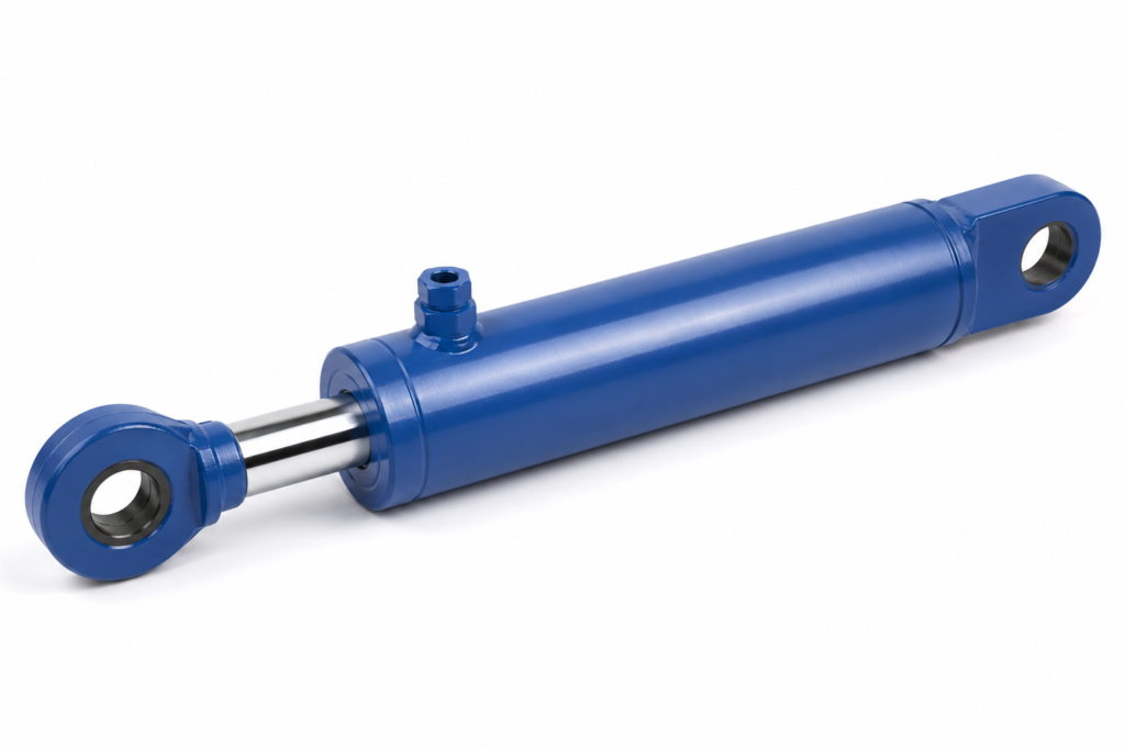
Why do hydraulic cylinders move heavy loads with compact parts?
A hydraulic cylinder moves heavy loads because pressurized oil acts over a piston area, turning pressure into linear force. The larger the bore, the larger the piston area; the higher the allowable pressure, the greater the force, provided the cylinder, hoses, valves, mounts, and machine structure are rated for it.
The technical observation that matters most is simple: oil pressure does not “push faster” by itself. It creates load-carrying force. Speed comes from how much oil volume the pump and valve can deliver to the cylinder chamber per second. This distinction is the foundation of safe hydraulic cylinder working analysis.
For an engineering buyer, this matters before a quotation is requested. If a lift table, press fixture, agricultural attachment, or industrial clamp feels weak, the first correction is not automatically a larger pump. The proper decision path is to calculate required force, confirm system pressure limits, then decide whether bore, pressure, mounting, or mechanical geometry must change.
In most practical systems, a cylinder is only one part of the force chain. The pump supplies flow, the relief valve limits pressure, the directional valve sends oil to the extend or retract side, and the load reacts through the rod end, clevis, trunnion, or flange. If any element is undersized, the machine may stall, drift, overheat, bend a rod, or overload a structure that was never designed for the new force level.
Key Takeaways
- Pressure creates force; flow creates cylinder speed, so a weak cylinder and a slow cylinder require different fixes.
- Extension force uses full piston area, while retraction force is lower because the rod area reduces the effective area.
- Stroke is the available travel distance, not a force rating, and it must match the machine geometry with safety margin.
- If force is too low, increase bore or pressure only after checking system ratings, standards, mounts, and buckling risk.
- ISO 4413 requires hydraulic systems to address foreseeable hazards, pressure control, leakage, and safe maintenance.
What happens inside the cylinder when oil enters the port?
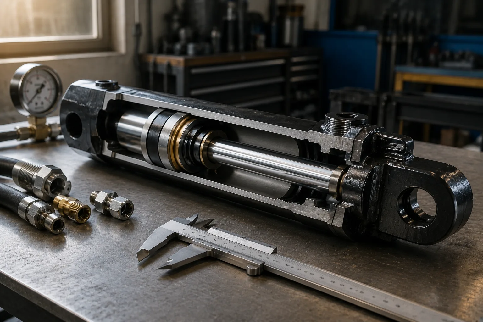
Oil entering a cylinder port fills one chamber and pushes against the piston, while oil on the opposite side exits through another port. In a double-acting cylinder, the valve decides which side receives pressure, so the rod can extend or retract under controlled power in both directions.
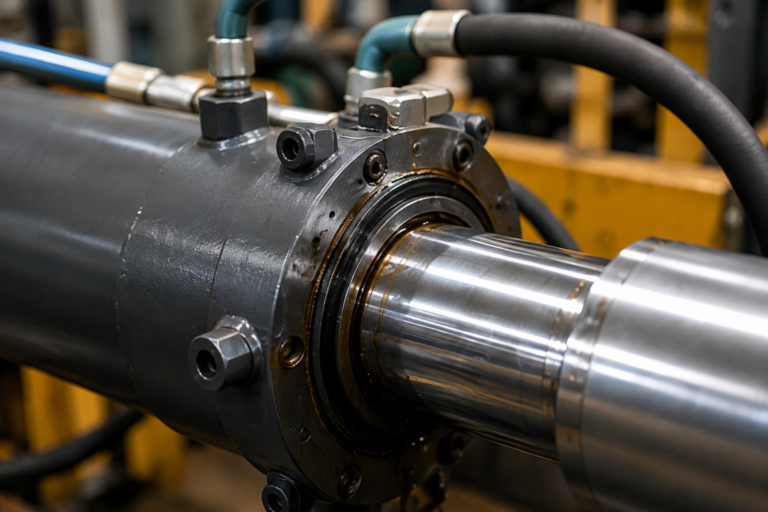
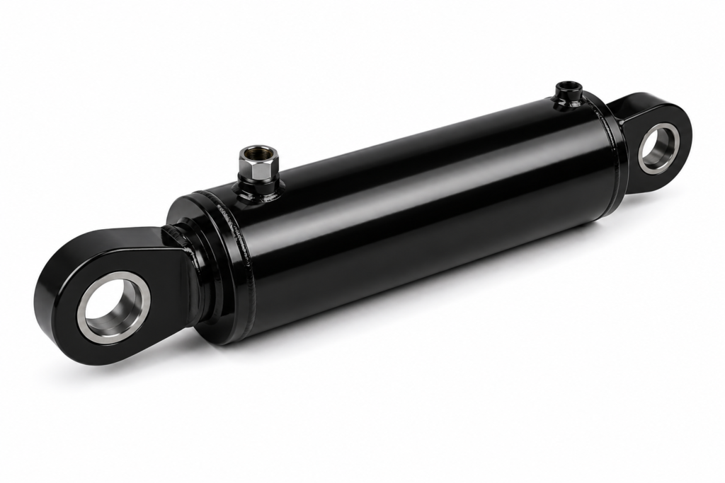
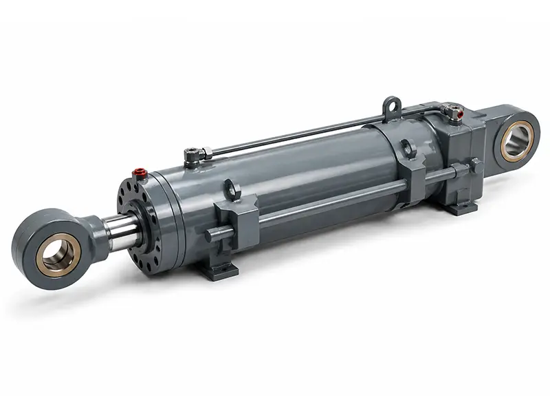
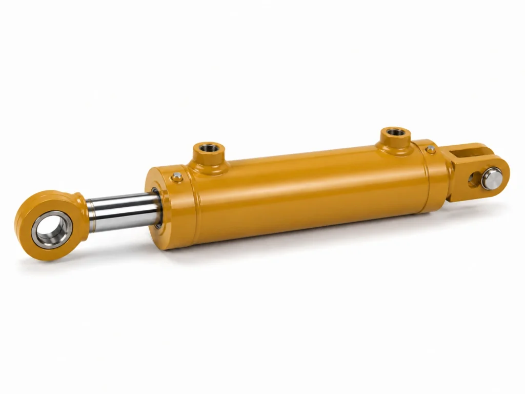
The main internal parts are the barrel, piston, rod, rod gland, seals, wear rings, ports, and end caps. The barrel provides the pressure-containing bore. The piston separates the extend and retract chambers. The rod transmits the force outside the cylinder. Seals reduce internal bypass and external leakage, while wear rings guide the piston and protect metal surfaces from contact.
In hydraulic ram working, the same pressure-area logic applies, but the term “ram” is often used for simple pushing or lifting cylinders, including single-acting designs. A single-acting cylinder normally uses hydraulic pressure in one direction and gravity, spring force, or load force for return. A double-acting cylinder uses oil pressure for both extension and retraction, making it more suitable for controlled machinery motion.
Oil is commonly treated as nearly incompressible for practical sizing, but real systems still flex. Hoses expand, oil compresses slightly under pressure, valves create pressure drop, and trapped air makes motion spongy. That is why commissioning often includes bleeding, pressure testing, stroke verification, and leak inspection before the equipment is accepted for production use.
Which terms must be clear before sizing a hydraulic cylinder?
The safest way to understand how does a hydraulic cylinder work is to separate four terms: pressure, flow, force, and stroke. These terms are often mixed in purchase requests, but each controls a different machine outcome and must be checked in the correct order.
- Pressure
- Pressure is the oil force per unit area, commonly expressed in psi, bar, or MPa. It is limited by the pump, relief valve, cylinder rating, hoses, fittings, seals, and applicable safety rules.
- Flow
- Flow is the oil volume delivered over time, commonly expressed in L/min or gpm. Flow mainly determines cylinder speed when the cylinder area is known.
- Force
- Force is the linear push or pull created by pressure acting on piston area. Extension force is usually higher than retraction force in a single-rod double-acting cylinder.
- Stroke
- Stroke is the rod travel from fully retracted to fully extended. It controls reach, lift height, clamp travel, or press travel, but it does not directly increase force.
- Bore
- Bore is the inside diameter of the cylinder barrel. Bore controls piston area, so increasing bore is a direct way to increase force at the same pressure.
These definitions also protect buyers from a common specification error: asking for “more pressure” when the real problem is slow cycle time, or asking for “more flow” when the real problem is insufficient force. The first risks unsafe pressure escalation; the second risks buying a larger power unit that still cannot move the load.
How do pressure and bore create cylinder force?
Force equals pressure multiplied by effective piston area. In inch units, extension force in pounds-force is pressure in psi multiplied by piston area in square inches. In metric units, force in newtons equals pressure in pascals multiplied by area in square meters.
The extension area of a round piston is calculated from bore diameter: area equals pi multiplied by bore squared, divided by four. Retraction force is lower because the rod occupies part of the piston area. For retraction, subtract rod area from piston area before multiplying by pressure.
For example, a 4-inch bore cylinder has about 12.57 square inches of piston area. At 2,000 psi, theoretical extension force is about 25,140 lbf before efficiency losses. If that cylinder has a 2-inch rod, the rod area is about 3.14 square inches, so effective retract area is about 9.43 square inches and theoretical retract force is about 18,860 lbf.
This is why the buyer decision logic must be firm: if force is too low, increase bore or pressure only after system limits are confirmed. Increasing bore raises force without raising pressure, but it also needs more oil volume for the same speed. Increasing pressure may use the existing package size, but it can exceed ratings and create compliance risk.
How do flow and area control cylinder speed?
Flow controls speed because the cylinder must be filled with oil volume to move. For a fixed flow rate, a smaller cylinder area moves faster and produces less force; a larger area moves slower and produces more force at the same pressure.
This is the most expensive misunderstanding in cylinder pressure and flow discussions. A pump with higher flow can make a cylinder move faster, but it does not automatically increase available pushing force. If the load requires more force than pressure multiplied by area can provide, the cylinder will still stall even if the pump is larger.
In inch units, speed in inches per second can be estimated by converting gpm to cubic inches per second, then dividing by effective cylinder area. One U.S. gallon is 231 cubic inches, so 1 gpm equals about 3.85 cubic inches per second. A 10 gpm flow into a 12.57 square inch extension area gives roughly 3.06 inches per second before losses and valve restrictions.
The same cylinder retracts faster than it extends if the same flow is sent to the rod side, because the effective retract area is smaller. This can be useful for fast return strokes in presses, clamps, and lifting mechanisms. It can also surprise operators if speed control valves, cushioning, and end-of-stroke deceleration are not correctly specified.
What parameters should an engineering buyer compare first?
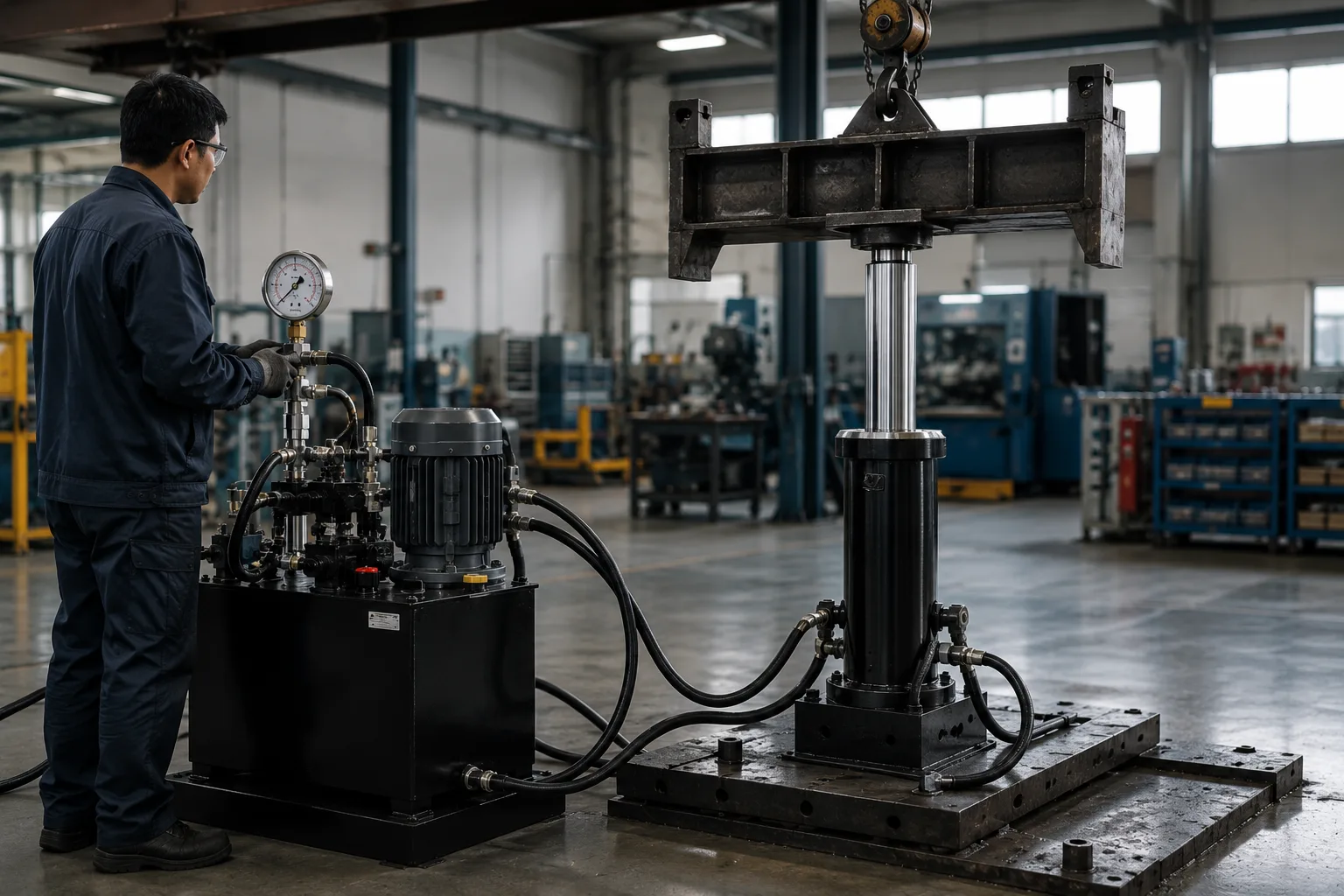
Compare bore, rod diameter, stroke, rated pressure, mounting style, speed requirement, and environment before comparing price. A low-cost cylinder with the wrong rod ratio or mount can fail earlier than a better-matched standard cylinder, especially under side load or long-stroke compression.
| Situation | Primary parameter to check | Preferred correction | Risk if misunderstood | Relevant reference basis |
|---|---|---|---|---|
| Cylinder cannot lift or press the load | Pressure, bore, mechanical leverage | Increase bore or confirmed safe pressure rating | Oversized pump still stalls because force is insufficient | Pressure-area force equations; ISO 4413 safety principles |
| Cylinder moves too slowly | Flow rate, valve capacity, hose restriction | Increase flow path capacity or reduce effective area if force allows | Unnecessary pressure increase creates heat and hazard | Flow-area speed equations; hydraulic power calculation |
| Rod bends in long extension | Rod diameter, stroke, mounting alignment | Use larger rod, shorter unsupported length, or guided structure | Buckling, seal wear, side-load damage | Manufacturer buckling charts; ISO mounting dimensions |
| Cylinder reaches end too harshly | Speed, load inertia, cushioning | Add adjustable cushioning, flow control, or deceleration logic | End-cap impact, pin wear, structure shock | ISO 4413 hazard reduction and safe operation requirements |
| Cylinder fits physically but leaks early | Seal material, fluid compatibility, temperature, surface finish | Specify seals and rod coating for oil, temperature, and contamination | Warranty claims, downtime, contamination ingress | Manufacturer seal data; maintenance standards |
How to use this table: start with the “Situation” column that matches the machine symptom, then use the “Primary parameter” column to avoid changing the wrong component; when two corrections look close, choose the one that stays inside rated pressure and safety limits.
How do cylinder types change the working principle in real machines?
The pressure-area principle stays the same, but cylinder type changes control, return motion, mounting, and risk. A single-acting ram is simple for lifting; a double-acting cylinder is better for controlled extension and retraction; telescopic cylinders provide long travel from a compact retracted length.
Single-acting cylinders for lifting and simple return
Single-acting cylinders are common where the load can return the rod by gravity or a spring. Dump trailers, simple jacks, and lift mechanisms often use this concept because only one pressure port is needed. The purchase risk is that return speed and return force are not powered unless a separate return mechanism exists.
Best for: vertical lifting or pushing applications where gravity return is reliable and controlled powered retraction is not required.
Double-acting cylinders for controlled machine motion
Double-acting cylinders are preferred for clamps, presses, steering functions, positioning systems, and OEM equipment that must push and pull. They need two oil paths and a directional valve, but they offer controlled motion in both directions. For buyers, this is usually the safer choice when the load direction changes or when retract control affects cycle time.
Best for: machinery that needs repeatable extension and retraction under load, especially where timing, alignment, or operator safety matters.
Telescopic cylinders for long stroke in short packages
Telescopic cylinders use nested stages to produce a long stroke from a shorter closed length. They are useful in dump bodies and space-constrained lifting equipment. The tradeoff is that force and speed can change by stage because effective areas are different, so the motion may not feel uniform unless the system is designed for it.
Best for: mobile equipment that needs long reach but cannot fit a conventional single-stage cylinder of the same stroke.
Which standards and safety rules affect hydraulic cylinder working?
Hydraulic cylinders are mechanical power components, so sizing must follow more than a formula. ISO 4413:2010 sets general rules and safety requirements for hydraulic fluid power systems, including pressure control, component selection, leakage considerations, and maintenance safety.
ISO 6020 and ISO 6022 series standards define mounting dimensions for certain single-rod hydraulic cylinders at nominal pressure classes such as 16 MPa and 25 MPa series. These standards help interchangeability, but they do not replace application engineering. A standard mounting envelope can still fail if side load, buckling, speed, contamination, or duty cycle is ignored.
For machines sold into the European market, Regulation (EU) 2023/1230 on machinery reinforces the need to address safety risks in machine design. In the United States, OSHA lockout/tagout rule 29 CFR 1910.147 is relevant to servicing equipment where stored hydraulic energy may create unexpected movement.
ZHY typically asks buyers for load, pressure, stroke, speed, mount, duty cycle, and environment because these items connect directly to standards-based risk control. The goal is not to make the cylinder more complicated; it is to prevent a technically correct force calculation from becoming an unsafe installed machine.
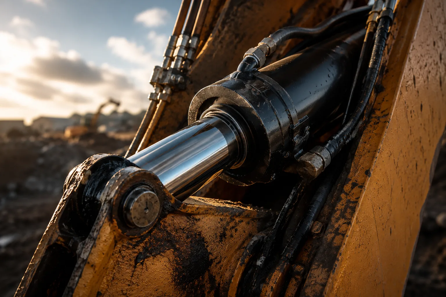
What industry trends are changing cylinder selection?
Hydraulic cylinder selection is moving toward higher efficiency, cleaner operation, better condition monitoring, and more documented compliance. Buyers increasingly ask not only whether the cylinder can lift the load, but whether it can do so with less leakage, less heat, easier maintenance, and predictable replacement planning.
Electro-hydraulic control is one clear trend. Position sensors, proportional valves, and electronic controllers allow smoother acceleration, deceleration, and repeatable stroke positions. This is useful in agricultural implements, construction machinery, presses, and automated fixtures where uncontrolled end impact shortens component life.
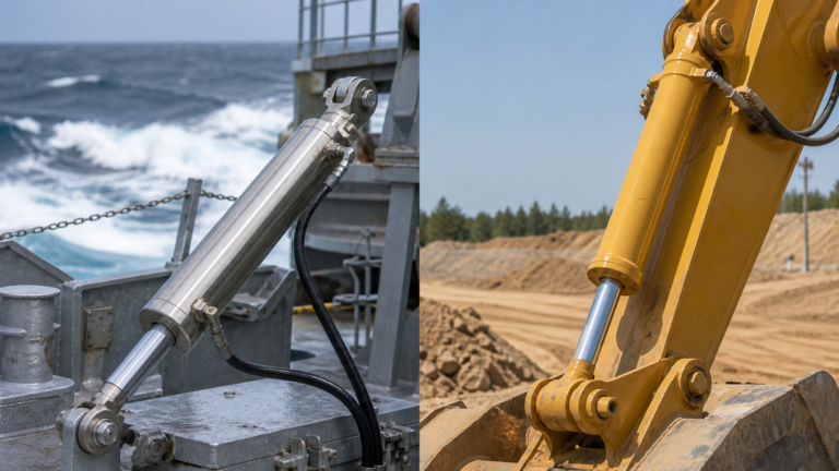
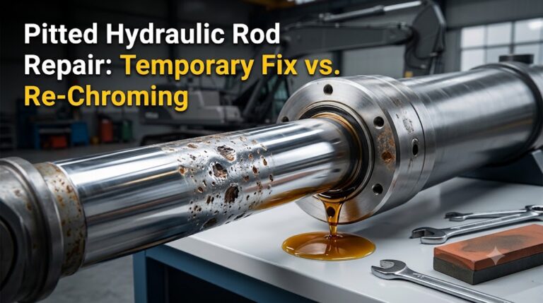
Another trend is stronger attention to contamination control. Cylinder seals and rods fail faster when oil carries abrasive particles or water, even when the force calculation is correct. Engineering buyers now often request rod coatings, wipers, corrosion resistance, and seal compounds suited to outdoor machinery, washdown areas, marine equipment, or high-cycle industrial lines.
The commercial implication is clear: a cylinder is no longer purchased only by bore and stroke. Procurement teams need enough technical detail to compare lifecycle risk. ZHY can support early selection by checking whether the requested bore, pressure, rod size, and stroke fit the application rather than quoting a dimension that later proves unsuitable.
What practical sizing workflow prevents the pressure-versus-speed mistake?
The best workflow is to calculate load force first, then calculate speed from flow, then verify stroke, mounting, rod stability, pressure rating, and environment. This sequence prevents the common error of solving a force problem with pump flow or solving a speed problem with pressure.
- Define the load case. Ask what maximum load must be lifted, pushed, pulled, clamped, or tilted. Include friction, linkage angle, acceleration, and any off-center load instead of using only static weight.
- Set the available system pressure. Check pump rating, relief valve setting, hose and fitting ratings, cylinder pressure class, and machine structure limits. Do not use theoretical pump maximum as the design pressure without confirmation.
- Calculate required bore. Divide required force by allowable working pressure, then convert area to bore. Add a practical margin for losses and real operating variation.
- Check retract force separately. Subtract rod area from piston area when the machine must pull, lower under control, unclamp, or retract against load.
- Calculate flow for speed. Multiply effective area by target speed to estimate required flow. Then check valve capacity, hose size, pressure drop, and heat generation.
- Confirm stroke and closed length. Match full travel to machine geometry and leave clearance for stops, cushioning, sensor brackets, and maintenance access.
- Check rod buckling and side load. Long-stroke compression cylinders need rod stability review. If side load exists, add guides or redesign the linkage rather than expecting the cylinder to act as a structural guide.
- Request a documented quotation. Ask the supplier for bore, rod, stroke, rated pressure, seal material, mounting dimensions, port type, test pressure, coating, and packaging details.
Practical asset: copy-ready hydraulic cylinder requirement checklist
Use this checklist before sending a cylinder inquiry. It is designed for engineering buyers, OEM procurement teams, and maintenance teams replacing a cylinder under time pressure. The goal is to give the supplier enough information to verify fit, force, speed, and risk before production.
- State the function first. Write whether the cylinder lifts, clamps, presses, steers, tilts, ejects, levels, or retracts a load. Include whether force is needed on extension, retraction, or both.
- Provide the load value and direction. Send the maximum load, linkage sketch, pivot distances, and worst operating angle. If the load changes through the stroke, mark the highest-force position.
- Give pressure limits. Provide normal working pressure, relief valve setting, and maximum allowed component pressure. Ask the supplier to confirm the cylinder rated pressure and test practice.
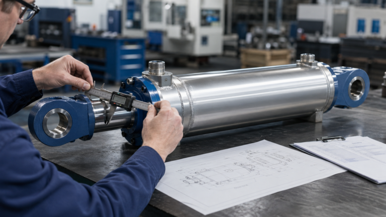
- Specify stroke and installation space. Send required stroke, closed length limit, open length limit, mount-to-mount dimension, and any surrounding interference.
- Define speed or cycle time. Give target extension time and retraction time. Also provide available pump flow and valve size, because these control real speed.
- Describe the environment. Note temperature, dust, water, salt spray, chemicals, outdoor exposure, and duty cycle. Ask for suitable rod coating, wiper, seal material, and corrosion protection.
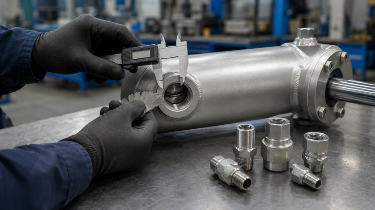
- Ask for mounting and port confirmation. Require drawings showing bore, rod, stroke, pin size, port type, port position, mount style, and tolerances.
- Request acceptance documents. Ask for pressure test confirmation, dimensional inspection, packaging method, and any applicable ISO-based design references before approving bulk production.
FAQ
1. How does a hydraulic cylinder work in simple terms?
A hydraulic cylinder works by using pressurized oil to push a piston inside a barrel. The piston is connected to a rod, so when oil enters one side, the rod moves in a straight line. Pressure determines how much force the cylinder can create, while oil flow determines how fast it moves. In a double-acting cylinder, oil can drive both extension and retraction through two ports.
2. Does higher hydraulic pressure make a cylinder faster?
No. Higher pressure mainly increases available force, not speed. Cylinder speed is mainly controlled by flow rate and effective piston area. A pump with more flow can move the cylinder faster if valves, hoses, and ports can pass that flow safely. Raising pressure to solve a speed problem can create unnecessary heat, component stress, and safety risk, especially if the relief valve and cylinder ratings are exceeded.
3. Why is retraction force lower than extension force?
Retraction force is lower in a single-rod double-acting cylinder because the rod occupies part of the piston area. During extension, pressure acts on the full piston area. During retraction, pressure acts only on the annular area, which is piston area minus rod area. The same pressure therefore produces less pulling force on retract, although retract speed is often faster with the same flow.
4. What information should I send before ordering a hydraulic cylinder?
Send load, working pressure, required force direction, stroke, closed length, speed or cycle time, mounting style, pin dimensions, port type, operating temperature, and environment. If the cylinder is part of a linkage, send a sketch or drawing with pivot distances. For ZHY or any technical supplier, this information allows the engineer to check force, speed, rod stability, mounting fit, and seal suitability before quoting.
5. Which standard is important for hydraulic cylinder safety?
ISO 4413:2010 is a key international standard for hydraulic fluid power systems because it covers general rules and safety requirements, including pressure control, component selection, leakage, and maintenance safety. ISO 6020 and ISO 6022 series standards are also relevant for standardized cylinder mounting dimensions. For machine maintenance, OSHA 29 CFR 1910.147 is important in the United States because stored hydraulic energy can cause unexpected movement during servicing.
References
- ISO 4413:2010 Hydraulic fluid power — General rules and safety requirements for systems and their components, International Organization for Standardization, ISO, 2010.
- ISO 6020-1:2007 Hydraulic fluid power — Mounting dimensions for single rod cylinders, 16 MPa series — Part 1: Medium series, International Organization for Standardization, ISO, 2007.
- ISO 6022:2018 Hydraulic fluid power — Mounting dimensions for single rod cylinders, 25 MPa series, International Organization for Standardization, ISO, 2018.
- The Hydraulic Trainer Volume 1: Basic Principles and Components of Fluid Technology, Bosch Rexroth Didactic, Bosch Rexroth, 2017.
- Industrial Cylinder Products Catalog, Parker Cylinder Division, Parker Hannifin Corporation, 2023.
- 2023 NFPA Technology Roadmap: Improving the Design, Manufacture and Function of Fluid Power Components and Systems, National Fluid Power Association, NFPA, 2023.
- 29 CFR 1910.147 The control of hazardous energy lockout/tagout, Occupational Safety and Health Administration, U.S. Department of Labor, 1989.
- Regulation (EU) 2023/1230 on machinery, European Parliament and Council of the European Union, Official Journal of the European Union, 2023.
How should buyers connect cylinder theory to a safer purchasing decision?
The practical answer is to treat a hydraulic cylinder as a controlled energy converter, not as an isolated steel tube. It converts oil pressure into linear force, but that force is only safe when the cylinder rating, system pressure limit, mounting geometry, rod stability, seals, and maintenance method are compatible with the real machine.
Why does this matter commercially? A cylinder that is too small will stall or run near relief pressure, wasting energy and generating heat. A cylinder that is too large may move too slowly with the existing pump, increase oil demand, and create unnecessary structure loads. A pump selected only for speed may raise cost without solving a force shortage. These are not theoretical mistakes; they appear in lift equipment, presses, mobile linkages, and retrofit projects where the original load calculation was incomplete.
What option should buyers choose when performance is marginal? If the load is too high for the current cylinder, first verify actual working pressure and relief settings, then check whether bore can be increased within the machine envelope. If the speed is too low but force is adequate, evaluate flow, valve capacity, hose size, and allowable heat before changing the cylinder. If the stroke is correct but the rod wears or bends, focus on alignment, side-load control, rod diameter, and guiding structure.
Standards add another layer of decision quality. ISO 4413:2010 emphasizes safe hydraulic system design, while ISO 6020 and ISO 6022 help buyers discuss standardized mounting dimensions. OSHA lockout/tagout requirements in 29 CFR 1910.147 remind maintenance teams that stored hydraulic energy can move equipment unexpectedly. These references support a clear purchasing position: the best cylinder is not simply the highest-pressure or lowest-price option; it is the one whose force, speed, stroke, mounting, and safety documentation match the machine duty.
For TOFU readers asking about hydraulic ram working, the central idea is this: pressure supplies strength, flow supplies motion, and stroke supplies travel. Once those roles are separated, the next step is no longer guesswork. A buyer can send load, pressure, stroke, and speed requirements to ZHY or another qualified manufacturer and receive a technically grounded recommendation rather than a dimension-only quotation.