Why does required load become pressure in a hydraulic cylinder?
Required load becomes hydraulic pressure because a cylinder converts fluid pressure into linear force through piston area. The practical formula is simple: pressure equals force divided by effective area, but the engineering decision is whether that pressure is safe for the whole circuit, not just mathematically possible.
A procurement manager or engineering buyer usually meets this problem when a machine is almost specified: the load is known, the available pump pressure is known, and the cylinder bore is still open for selection. The risky shortcut is to choose a small cylinder and raise pressure until the force number looks right. That can damage seals, overload hoses, and create stored-energy hazards.
The core relationship is:
Pressure = Force ÷ Area
In U.S. customary units, pressure is normally expressed as psi, force as pounds-force, and piston area as square inches. In metric engineering, pressure is usually expressed as bar or MPa, force as newtons or kilonewtons, and area as square millimeters or square meters. The relationship does not change; only the units change.
For a push stroke, use the full piston area. For a pull stroke on a single-rod cylinder, use annular area, meaning piston area minus rod area. That difference is why a cylinder normally produces less force when retracting than when extending at the same pressure.
In MOFU buying decisions, the calculation is not an academic exercise. It directly affects bore size, rod diameter, seal material, pump rating, valve selection, hose class, frame strength, delivery cost, and machine safety documentation. ZHY normally asks for maximum system pressure and load condition first because those two inputs prevent most sizing errors before a quotation is prepared.
What is the basic hydraulic cylinder pressure calculation?
The basic hydraulic cylinder pressure calculation is to divide the required cylinder force by the effective piston area. For extension, use piston bore area; for retraction, subtract rod area from piston area. Add friction, load angle, acceleration, and a safety margin before choosing the final working pressure.
Use this sequence for a push application:
- Identify the required load force, including the weight, tooling force, clamp force, or resistance force.
- Convert the load into a consistent force unit such as lbf, N, or kN.
- Calculate piston area from bore diameter using area = π × diameter² ÷ 4.
- Divide force by area to obtain theoretical pressure.
- Add realistic allowance for friction, pressure drop, side load, dynamic impact, and uneven loading.
- Compare the result with cylinder, pump, valve, hose, fitting, and seal ratings.
Example: a cylinder must push 20,000 lbf. If the bore is 4 inches, piston area is 12.57 in². The theoretical pressure is 20,000 ÷ 12.57 = about 1,592 psi. If the application includes sliding friction, guide resistance, and pressure drop, the selected operating pressure may need to be higher. However, that higher value must remain below the rated working pressure of every pressure-containing component.
For a retracting load, assume the same 4-inch bore with a 2-inch rod. Piston area is 12.57 in² and rod area is 3.14 in², so annular area is 9.43 in². The same 20,000 lbf pull would require about 2,121 psi before losses. This is a common reason why a cylinder that looks strong enough on extension may fail the retract force requirement.
According to ISO 4413:2010, hydraulic systems should be designed to prevent hazardous operation and control pressure-related risks. That principle changes the buying logic: never treat calculated pressure as permission to exceed a component’s rated limit.
Key Takeaways
- Pressure is force divided by effective piston area, so bore size is the main lever when available pressure is limited.
- Extension force uses full piston area, while retraction force uses annular area after subtracting rod area.
- If the calculated pressure approaches system limits, increase cylinder bore instead of forcing the pump, seals, hoses, and valves above rating.
- Working pressure selection should include friction, pressure drop, load angle, duty cycle, and shock conditions.
- ISO 4413 and OSHA lockout principles reinforce that pressure calculations must be tied to safe circuit design and maintenance control.
Which area should you use for push, pull, and holding force?
Use full piston area for push force, annular area for pull force, and the load-side effective area for holding force. The correct area depends on which chamber is pressurized and whether the rod reduces the fluid area available to create motion.
- Bore area
- The circular piston area created by the cylinder bore. It is used for extension force in a conventional single-rod cylinder.
- Rod area
- The cross-sectional area of the piston rod. It reduces effective area on the rod side of a single-rod cylinder.
- Annular area
- The piston area minus rod area. It is used for retract force and explains why pull force is usually lower than push force at the same pressure.
- Working pressure
- The pressure expected during normal operation, after considering load, friction, pressure drop, and duty cycle, but still below rated component limits.
For vertical lifting, include the dead weight of the load, lifting attachment, moving fixture, and any mechanical linkage losses. For horizontal pushing, include sliding friction, cutting resistance, forming resistance, or clamping force. For holding, include whether the cylinder must resist gravity, back-driving, thermal expansion, or external shock.
The buyer decision is direct: if available pressure is limited, increase bore rather than exceeding system rating. A larger bore creates more force at the same pressure. The trade-off is slower speed for a given pump flow and a larger oil volume requirement, but those consequences are usually easier to manage than damaged seals or unsafe overpressure.
How do bore size and system pressure change the buying decision?
Bore size and system pressure move in opposite directions: a larger bore lowers required pressure, while a smaller bore raises it. The better selection is the one that delivers the required force within the rated pressure of every component and still leaves margin for real operating losses.
| Situation | Recommended decision | Reason | Procurement check |
|---|---|---|---|
| Calculated pressure is far below rated system pressure | Keep the bore if speed, envelope, and cost are acceptable. | The cylinder has adequate pressure headroom for friction and pressure drop. | Confirm seal material, duty cycle, and test pressure documentation. |
| Calculated pressure is close to rated working pressure | Increase bore or reduce load through mechanical advantage. | Small real-world losses may push the system above safe operating limits. | Ask for maximum allowable working pressure of cylinder, hose, valve, and fittings. |
| Retract force is the limiting case | Check rod diameter and annular area before approving drawings. | A thick rod improves buckling resistance but reduces retract force area. | Request extension and retraction force values at the same pressure. |
| Shock, impact, or frequent cycling is expected | Add margin and consider cushions, accumulators, or controlled valves. | Dynamic loads can create pressure spikes higher than steady calculations. | Review relief valve setting, duty cycle, and maintenance access. |
| Machine envelope limits cylinder diameter | Do not automatically raise pressure; review full circuit rating first. | Compact packaging can create pressure and heat problems if not engineered. | Ask supplier to verify pressure rating, rod buckling, and mounting loads together. |
How to use this table: read the first column as the project condition, then use the second column as the preferred action; when two options look similar, prioritize the row that protects rated pressure limits before speed, compactness, or initial purchase cost.
The most common mistake is treating pump pressure as the only limit. A power unit may be capable of high pressure, but the weakest rated item could be a hose, port adapter, valve body, welded fitting, rod seal, or old cylinder tube. ISO 4413 emphasizes safe system design, and OSHA 29 CFR 1910.147 highlights the broader risk of hazardous energy during servicing. Together, they support conservative pressure selection and controlled maintenance procedures.
For example, if a compact press needs 50 kN and a proposed bore requires pressure too close to the relief valve setting, the safer sourcing answer is not “increase the relief valve.” The safer answer is to enlarge bore, revise linkage geometry, or split the load across multiple cylinders.
What real-world factors should be added before selecting working pressure?
Real-world pressure should include more than static load. Add allowances for friction, line loss, valve pressure drop, uneven loading, acceleration, side load, temperature, contamination, and shock. This is where working pressure selection becomes a safety and reliability decision.
Friction appears in guide rails, pins, bushings, seals, sliding shoes, and workpiece contact. Pressure drop appears in directional valves, flow controls, hoses, quick couplers, filters, manifolds, and undersized ports. Dynamic effects appear when the load starts suddenly, stops abruptly, hits an end stop, or reverses direction under gravity.
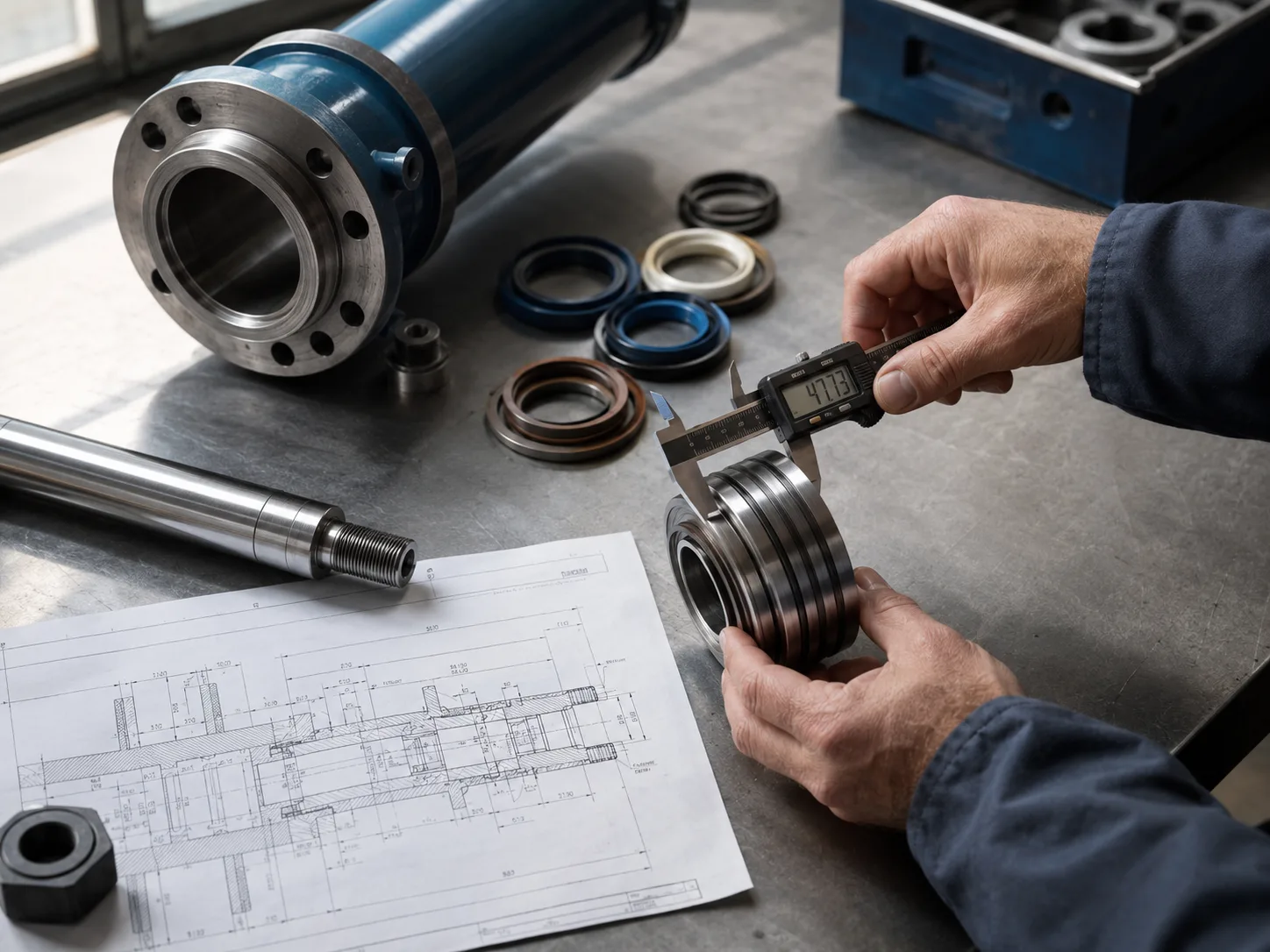
Material and product parameters matter too. Cylinder tubes must have suitable wall thickness and internal finish. Rods need enough diameter for buckling resistance and enough surface hardness or coating quality for seal life. Seals must match fluid type, temperature, pressure, and cycle speed. Mountings must handle side loads, because a cylinder is designed mainly for axial force, not bending.
Industry practice is also moving toward more documented sizing. Buyers increasingly ask for calculation sheets, rated pressure declarations, factory pressure test records, seal material confirmation, and traceable drawings. This trend is driven by export projects, equipment safety audits, and the cost of downtime when a hydraulic actuator fails in production.
For a ZHY review, the most useful information is not a vague load description. It is the maximum load, direction of force, stroke, speed, duty cycle, available system pressure, mounting style, working temperature, fluid type, and whether the cylinder pushes, pulls, clamps, lifts, or holds.
How should a buyer avoid overpressure, seal damage, and safety hazards?
A buyer avoids overpressure by treating the calculated value as a minimum requirement, then validating it against rated pressure, relief settings, component compatibility, and maintenance risk. Raising pressure beyond component limits is the wrong correction for an undersized cylinder.
Seal damage usually starts before catastrophic failure. Excess pressure can extrude seals, increase friction, generate heat, accelerate wear, and cause leakage past the piston or rod gland. Pressure spikes can also loosen fittings, fatigue welds, and make hoses more dangerous during servicing. The hazard is not only lost performance; it is uncontrolled movement and stored hydraulic energy.
Use these checks before approving a cylinder:
- Confirm whether the force requirement is for extension, retraction, or holding.
- Ask for rated working pressure and factory pressure test method.
- Check whether the calculated pressure includes friction and pressure drop.
- Verify that hoses, valves, fittings, manifolds, and seals match the same pressure class.
- Review relief valve setting and whether transient spikes are expected.
- Check rod buckling for long-stroke compression applications.
- Confirm that maintenance procedures isolate and release hydraulic energy.
The correct commercial stance is strict: if the pressure required to move the load exceeds the system rating, the design is not acceptable. Increase bore, reduce load, change linkage geometry, use multiple cylinders, or redesign the mechanism. Do not ask the operator to compensate with a higher relief setting.
Copy-ready pressure calculation and sourcing checklist
This checklist turns the calculation into an approval workflow. Use it before sending an inquiry, comparing offers, or signing off a cylinder drawing.
- Write the load case first: state whether the cylinder must lift, push, pull, clamp, press, or hold, and identify the worst-case load direction.
- Record the maximum required force in one unit system, such as kN or lbf, and include tooling weight, fixture weight, friction, and external resistance.
- List available hydraulic pressure from the power unit, then separately list the rated pressure of the cylinder, hoses, valves, fittings, and seals.
- Calculate extension pressure using piston bore area, then calculate retraction pressure using annular area if pull force matters.
- Ask the supplier to show the formula, bore, rod diameter, effective area, theoretical force, and selected working pressure on one calculation sheet.
- Check whether long-stroke compression needs rod buckling verification, especially for vertical lifts, presses, tilting frames, or unsupported rod travel.
- Request confirmation of seal material, fluid compatibility, temperature range, and expected duty cycle instead of accepting only a cylinder model number.
- Ask for pressure test records, drawing revision number, port size, mounting dimensions, and packaging method before approving bulk production.
- Compare offers by rated pressure margin and documentation quality, not only by unit price.
- If calculated pressure is close to the rating, ask ZHY or another qualified supplier for a revised bore option before changing relief settings.
FAQ
1. What is the formula for hydraulic cylinder pressure?
The formula is pressure equals force divided by effective area. For extension, effective area is the full piston bore area. For retraction on a single-rod cylinder, effective area is piston area minus rod area. This means the same cylinder usually produces less pulling force than pushing force at the same pressure. The formula gives theoretical pressure, so the final working pressure should also account for friction, valve losses, hose losses, acceleration, and safety margin.
2. How do I calculate hydraulic cylinder pressure if the load is in kilograms?
Convert kilograms of mass into force before calculating pressure. For a vertical lift, multiply mass by gravitational acceleration, commonly 9.81 m/s², to obtain newtons. Then divide that force by the piston area in square meters to obtain pascals, or convert to bar or MPa for hydraulic selection. If the load moves through a linkage, include the mechanical ratio and worst-case angle. Do not use kilograms directly as pressure input because kilograms describe mass, not hydraulic force.
3. Should I increase pressure or increase bore size for a heavier load?
If available pressure is limited or the calculated value is close to system rating, increase bore size rather than raising pressure. A larger bore gives more piston area, so the same load can be moved at lower pressure. Raising pressure may overload seals, hoses, valves, fittings, and the cylinder tube. The trade-off is that a larger bore needs more oil volume, which may reduce speed unless pump flow is increased.
4. Why is retract force lower than extend force in many hydraulic cylinders?
Retract force is lower because the piston rod occupies part of the pressure area on the rod side. During extension, pressure acts on the full piston area. During retraction, pressure acts only on the annular area, which is piston area minus rod area. A larger rod can improve strength and buckling resistance, but it also reduces retract area. Buyers should check both directions when the machine must pull, lift back, or hold load during retraction.
5. What safety standards matter when selecting hydraulic working pressure?
ISO 4413:2010 is a key international standard for hydraulic fluid power systems and safety requirements. It focuses on reducing hazards through suitable design, control, and documentation. For maintenance, OSHA 29 CFR 1910.147 addresses control of hazardous energy in the United States, including stored energy that may be present in hydraulic equipment. These references support a conservative approach: calculate pressure, verify component ratings, control stored energy, and avoid exceeding rated limits.
References
- ISO 4413:2010 Hydraulic fluid power — General rules and safety requirements for systems and their components, International Organization for Standardization, ISO, 2010.
- 29 CFR 1910.147 The control of hazardous energy lockout/tagout, Occupational Safety and Health Administration, U.S. Department of Labor, current regulation.
- Hydraulic Fluid Power — Cylinders — Mounting Dimensions for Single Rod Cylinders, 16 MPa Compact Series, International Organization for Standardization, ISO 6020-2, 2015.
- Hydraulic Fluid Power — Cylinders — Mounting Dimensions for Single Rod Cylinders, 25 MPa Series, International Organization for Standardization, ISO 6022, 1981 with amendments.
- Fluid Power Basics, National Fluid Power Association, NFPA, ongoing educational resource.
- Hydraulic Cylinder Technical Information, Parker Hannifin Corporation, Parker Hannifin, product engineering resource.
- Hydraulic Cylinders for Industrial Applications, Bosch Rexroth AG, Bosch Rexroth, product and engineering catalog resource.
- Hydraulic Pressure and Force, Engineering ToolBox, Engineering ToolBox, engineering reference resource.
How this pressure calculation supports safer sourcing and better cylinder selection
The most useful way to read a cylinder pressure result is not as a single number, but as a decision signal. A low calculated pressure shows that the selected bore has enough area for the load. A high calculated pressure warns that the cylinder may be too small, the mechanical arrangement may be inefficient, or the circuit may be heading toward unsafe operating stress.
For engineering buyers, the “how” is straightforward: convert load into force, calculate effective area, divide force by area, and compare the result with rated pressure. The “why” matters more in purchasing. Hydraulic components fail when real operating pressure, pressure spikes, contamination, temperature, or misalignment exceed what the design can tolerate. ISO 4413:2010 frames hydraulic safety as a system responsibility, which means a cylinder cannot be approved in isolation from hoses, valves, fittings, relief devices, and maintenance procedures.
The best option under a limited pressure supply is usually a larger bore, not a higher relief setting. This choice may increase cylinder size and oil volume, but it lowers stress across the hydraulic circuit and gives more margin for friction and dynamic loads. If machine speed becomes too slow with the larger bore, the correct next consideration is pump flow or cycle-time redesign, not overpressure.
Market behavior also supports more disciplined selection. Export machinery, automated production lines, and maintenance-sensitive factories increasingly require documented calculations, pressure test records, and clear rated working pressure declarations. Buyers who compare only price often miss the expensive risks: early seal leakage, unstable motion, downtime, unsafe servicing, and rejected equipment audits.
The practical conclusion is firm: how to calculate hydraulic cylinder pressure is only the first step. The stronger buying decision is to use the result to protect component ratings, choose bore size intelligently, and ask suppliers for the exact maximum system pressure and load condition before production begins.