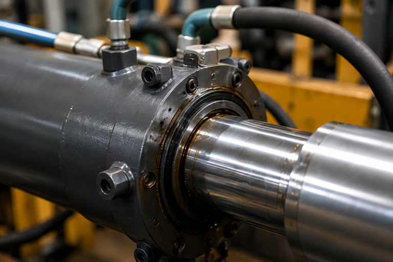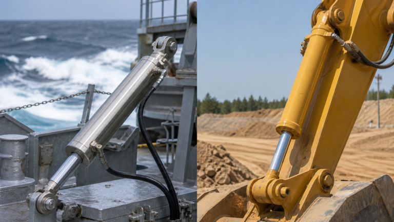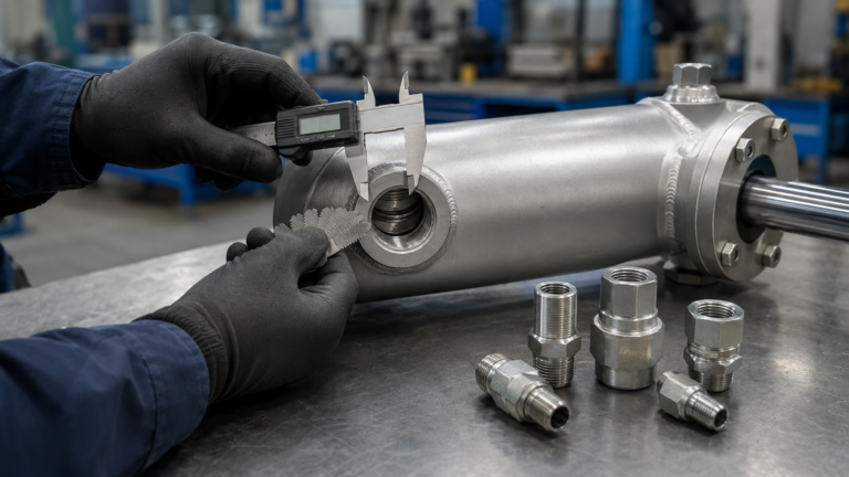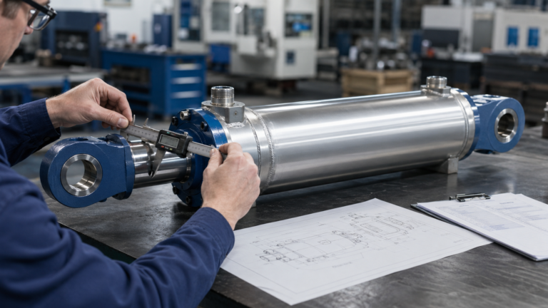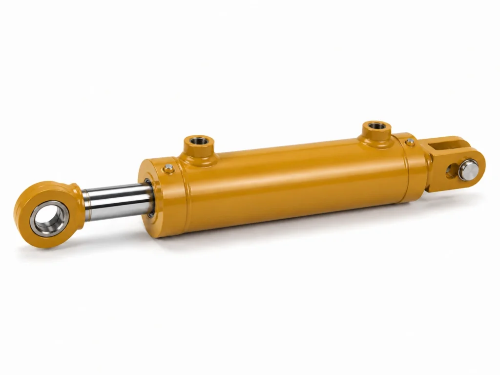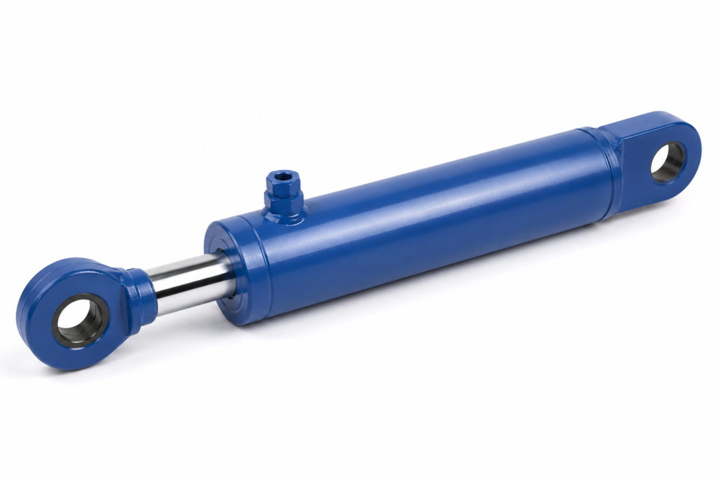
What goes wrong when buyers size the bore only?
The fastest way to get a bad cylinder quote is to specify only the bore and ignore the rod, stroke, and mounting. Bore creates push force, but the rod controls pull force, column stability, seal package space, and whether the cylinder survives side load in the real machine.
For a procurement manager or engineering buyer, the practical risk is not just an undersized cylinder. A cylinder with enough theoretical force can still bend a rod, chatter during movement, overload a clevis pin, or cost more than necessary because the supplier adds excess safety margin to cover missing information.
A better approach is to turn five inputs into an RFQ-ready logic chain: load, available pressure, required stroke, movement speed, and installation envelope. If the load is fixed and system pressure is known, calculate the bore first. Then confirm rod diameter against buckling risk, check retraction force, verify stroke allowance, and select a mounting style that keeps the load path straight.
This article is written for MOFU-stage engineering buyers, equipment builders, and procurement teams who already know the application but need a disciplined method before asking ZHY or another cylinder manufacturer for pricing. The goal is not to replace final engineering approval; it is to prevent avoidable quote revisions and early field failures.
What data do you need before starting hydraulic cylinder sizing?
You need load, pressure, stroke, speed, duty cycle, mounting space, and environmental conditions before useful hydraulic cylinder sizing can begin. Without those inputs, the bore calculation becomes a guess and every later decision, including rod diameter and mounting, is built on weak assumptions.
Start with the actual working load, not the nameplate weight alone. A lift table, press, clamp, compactor, or tilting fixture may experience friction, acceleration, shock, off-center loading, or mechanical disadvantage from linkage geometry. In many industrial RFQs, the force requirement should be stated as working force plus a stated safety factor rather than as a vague “heavy-duty” description.
Next, state the available system pressure. A cylinder designed for a 16 MPa industrial circuit is not the same quoting problem as a cylinder intended for a 25 MPa compact system. ISO 6020-1 is associated with 16 MPa single-rod cylinder mounting dimensions, while ISO 6022 covers 25 MPa single-rod mounting dimensions, so pressure class can influence both dimensions and supplier selection.
Speed also matters because it drives flow demand. Cylinder velocity is determined by flow divided by effective piston area, so a larger bore gives more force but requires more oil to move at the same speed. That can increase pump size, heat generation, hose sizing, and control valve requirements.
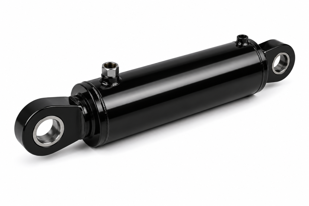
- Bore diameter
- The inside diameter of the cylinder barrel and the main driver of extension force because pressure acts over piston area.
- Rod diameter
- The diameter of the piston rod; it reduces retraction area and strongly affects buckling resistance in compression.
- Stroke
- The distance the rod must travel between fully retracted and fully extended positions, including real clearance and end-position tolerance.
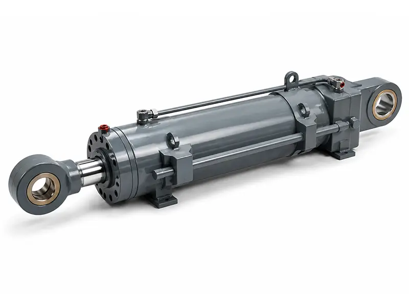
- Mounting centerline
- The intended load path through pins, flanges, trunnions, or feet; poor alignment increases side load and rod wear.
Key Takeaways
- Calculate bore from required force and available pressure before choosing a catalog cylinder size.
- Check rod diameter for compression buckling whenever the cylinder pushes a load over a long stroke.
- Confirm retraction force because rod area reduces the effective pull-side piston area.
- Use ISO 3320 metric bore and rod series as a reference point when standardization matters.
- Send load, pressure, stroke, speed, mounting envelope, and duty cycle together to make the RFQ usable.
How do you calculate bore from load and pressure?
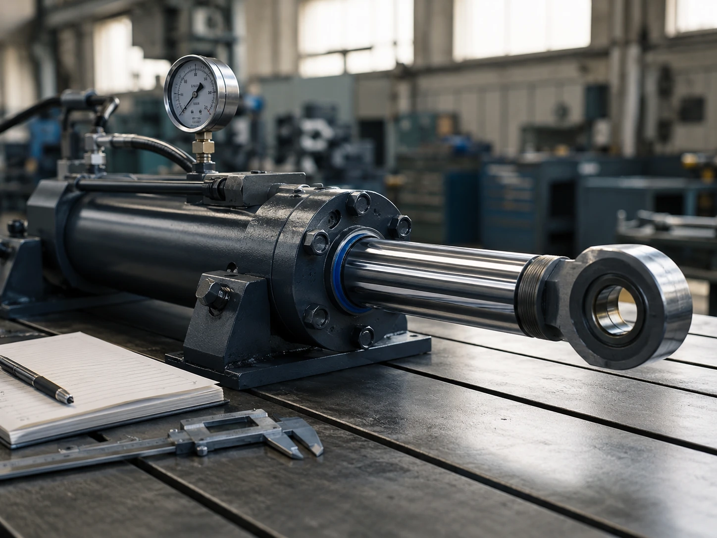
Calculate bore by dividing required cylinder force by available hydraulic pressure, converting that area into a piston diameter, and then rounding up to the next practical standard size. This is the first hard gate in how to size a hydraulic cylinder, but it is not the final selection.
The basic extension force relationship is Force = Pressure × Piston Area. For a circular piston, Area = π × Bore² ÷ 4. If the required push force is known, rearrange the formula to calculate the minimum bore. Then add an engineering margin for friction, pressure losses, wear, and load uncertainty.
For example, if a fixture needs 80 kN of push force and the usable working pressure is 16 MPa, the theoretical piston area is 80,000 N ÷ 16,000,000 Pa = 0.005 m². That area corresponds to a bore of about 79.8 mm, so an 80 mm bore may be the starting point before margin. If shock loads or linkage losses are expected, the next larger standard bore may be safer.
Do not calculate with maximum pump relief pressure unless the machine is intended to run there continuously. Many industrial systems have a relief setting higher than normal working pressure. Sizing against the relief number can produce a cylinder that looks correct on paper but underperforms during normal operation.
How should rod diameter and stroke be checked after bore selection?
After the bore is selected, check rod diameter against retraction force, buckling length, stroke, and mounting style. The rod is the structural column in compression, so a long-stroke push cylinder can fail even when the bore has enough hydraulic force.
For pull force, the effective area is the piston area minus the rod area. A larger rod improves stiffness and buckling resistance, but it reduces retraction force and may require more pressure to pull the same load. That tradeoff is central to bore stroke rod diameter decisions, especially on presses, compactors, vertical lifts, and clamp-release mechanisms.
Buckling risk rises with long unsupported rod length, compressive loading, and misalignment. A rear clevis with a front clevis may allow angular movement, but it also creates a pinned-pinned column condition. A rigid flange or trunnion arrangement can change the effective length and side-load behavior. Final rod buckling verification should use the supplier’s engineering charts or Euler-based calculations with the actual end condition.
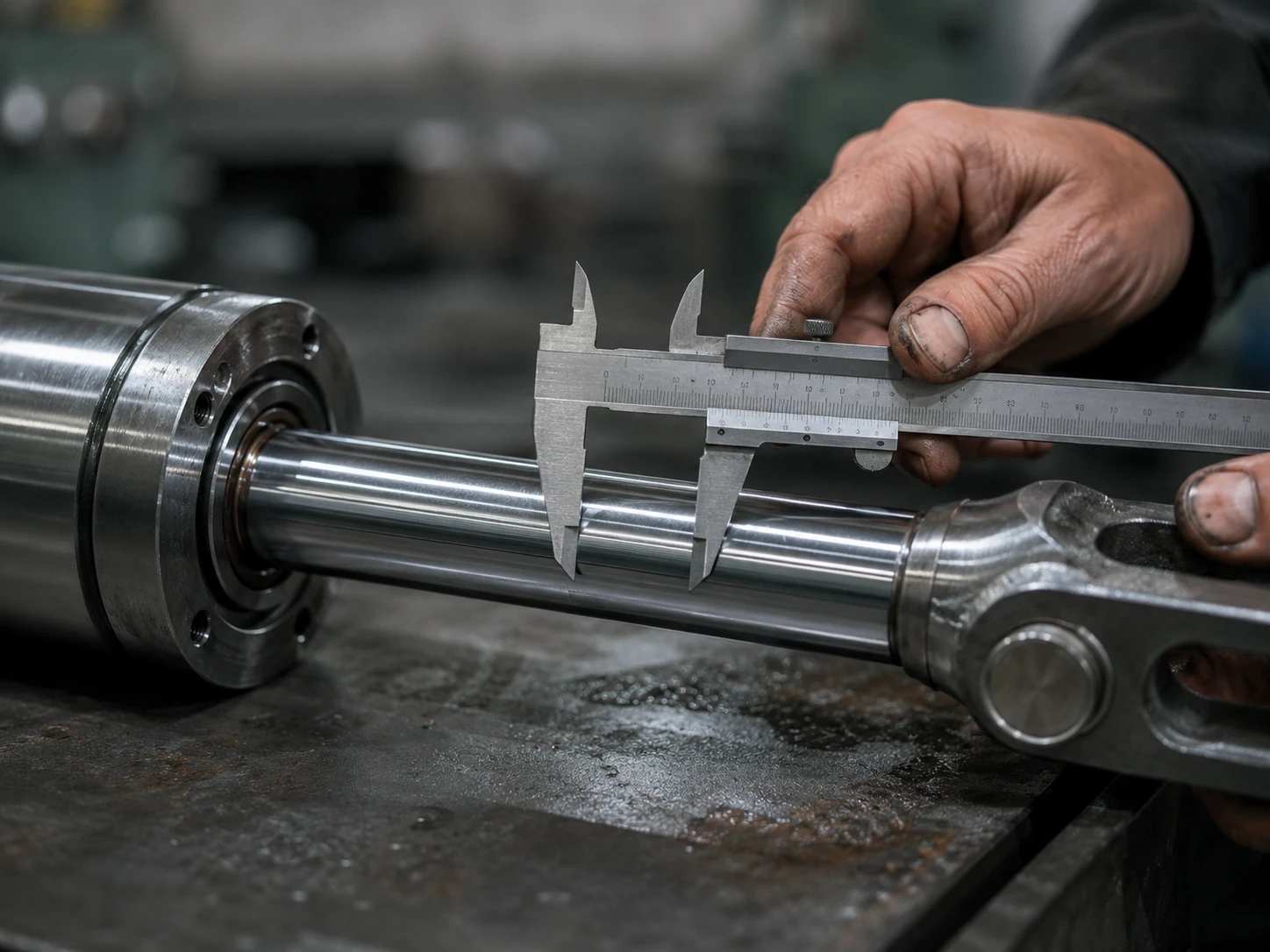
Stroke must be checked against the machine’s real travel, not only the nominal movement. Include end cushioning distance, mechanical stops, sensor brackets, maintenance access, and tolerance stack-up. If the cylinder bottoms internally before the machine reaches its external stop, rod threads, piston seals, or mounting pins can take impact loads they were not designed to absorb.
Which sizing checks should be included in an RFQ-ready decision table?
An RFQ-ready table should connect each machine condition to the cylinder parameter it controls. This prevents suppliers from quoting a bore-only cylinder when the real decision requires pressure class, rod stiffness, stroke clearance, mounting geometry, and operating speed to be reviewed together.
| Machine condition | Primary sizing check | What to send in the RFQ | Risk if ignored |
|---|---|---|---|
| Known push load and known working pressure | Calculate bore from force and pressure, then round to a standard series such as ISO 3320 metric bore references. | Required force in kN, working pressure in MPa or bar, safety factor, and whether the force is continuous or peak. | Undersized bore, slow force build-up, or pressure running near relief setting. |
| Long extension while pushing | Check rod diameter and effective unsupported length for buckling. | Stroke, mounting type, extended length, load direction, and whether side load or angular movement exists. | Bent rod, seal wear, scoring, unstable movement, or sudden column failure. |
| High pull force required | Verify annular retraction area after subtracting rod area from piston area. | Pull force requirement, rod diameter preference, pressure limit, and return speed target. | Enough push force but insufficient pull force during return or unclamping. |
| Fast cycle time | Check flow demand, port size, heat, valve capacity, and cushioning. | Required extend and retract speeds, cycle frequency, duty cycle, and oil supply conditions. | Oversized pump requirement, heat generation, cavitation, or harsh end-of-stroke impact. |
| Tight installation envelope | Confirm closed length, open length, pin centers, and mounting standard. | Installation drawing, maximum retracted length, maximum extended length, and nearby interference points. | Cylinder fits the calculation but not the machine. |
How to use this table: prioritize the column that matches the most severe machine condition; if two checks are close, choose the option that reduces failure risk before optimizing cost.
The table also makes supplier communication faster. Instead of asking for “one 80 mm bore cylinder,” the buyer can request “80 mm starting bore, 16 MPa working pressure, 600 mm stroke, compression push load, clevis mounting, and rod buckling review required.” That is the difference between a price inquiry and an engineering RFQ.
How do mounting style, alignment, and standards affect final selection?
Mounting style affects cylinder life because it defines how force enters the rod and barrel. A correctly sized bore can still fail early if the mount creates side load, pin binding, or angular misalignment during the stroke.
Clevis and spherical bearing mounts are useful when the cylinder must follow an arc, such as on a tilting frame or lifting linkage. Flange mounts are stronger for straight-line thrust where the machine frame is rigid and accurately aligned. Trunnion mounts help when the pivot point must sit near the cylinder body, but the frame must support the trunnion load without twisting.
Standards matter because they reduce ambiguity. ISO 6020-1 and ISO 6022 provide mounting dimensions for single-rod cylinders in defined pressure classes, while ISO 3320 gives metric series guidance for cylinder bores and piston rod diameters. These standards do not replace application engineering, but they help buyers and suppliers speak the same dimensional language.
Hydraulic safety and system integration should also be considered. ISO 4413 sets general rules and safety requirements for hydraulic fluid power systems, including system design and component considerations. Cleanliness is another practical factor: ISO 4406 provides a coding method for particle contamination in hydraulic fluids, which matters because abrasive contamination can shorten seal, rod, and valve life.
What material and quality details should engineering buyers verify?
Engineering buyers should verify rod material, tube quality, seal compatibility, porting, welding, surface finish, and test documentation before approval. These details do not change the basic force formula, but they determine whether the selected cylinder can repeat that force in real operating conditions.
Common hydraulic cylinder rods are made from hard chrome plated steel or corrosion-resistant alternatives where exposure demands it. Barrel tubes are often honed or skived and roller burnished to support sealing performance. ASTM A519 covers seamless carbon and alloy steel mechanical tubing, a common reference point when discussing tube material quality, although the final specification depends on pressure class and manufacturing route.
Seals must match hydraulic fluid, temperature, pressure, and duty cycle. A standard nitrile seal package may be suitable for many mineral oil systems, while high-temperature, low-temperature, water-glycol, or aggressive environments may require different elastomers. This is why fluid type and operating temperature should be included in the RFQ instead of being treated as afterthoughts.
Inspection evidence matters for bulk orders. Buyers should ask for pressure test requirements, dimensional inspection, weld inspection method where applicable, rod plating or surface treatment details, and packaging protection for the rod. For ZHY projects, a stronger RFQ usually includes the machine drawing, expected annual volume, sample quantity, and acceptance criteria before price negotiation starts.
What project scenario shows the full sizing logic?
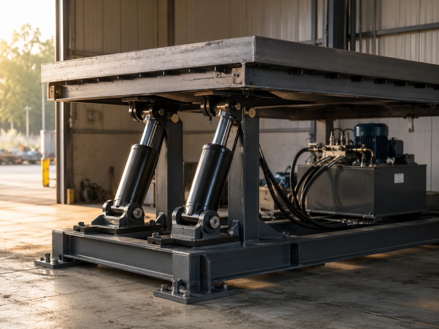
A compact lifting fixture shows why the right order is bore first, rod second, stroke third, mounting last. The buyer knows the platform load and pressure, but the final cylinder still depends on buckling length, synchronized movement, and installation clearance.
Consider a factory fixture that raises a steel platform for maintenance access. The load is stable, the hydraulic unit has a defined working pressure, and the required travel is known. A bore calculation gives the initial force capacity, but the cylinders push in compression during extension, so rod buckling becomes a major check once the stroke becomes long.
If the buyer only sends the load and asks for the smallest possible bore, suppliers may quote a compact cylinder with an economical rod. That may work in a short press stroke but fail in a long lift where the rod is extended under load. A better RFQ states the platform load, number of cylinders, linkage ratio if any, working pressure, stroke, closed length limit, mounting pin sizes, and whether the load is guided by rails.
The guided-rail detail is important. If the machine frame carries side load and the cylinder only pushes axially, a standard mount may be suitable. If the cylinder must also resist side force, the better answer is not simply a larger rod; the machine should be redesigned with guides or bearings so the cylinder is not used as a structural slide.
Practical Asset: copy this cylinder sizing checklist before asking for a quote
Use this sequence before contacting a supplier so the first quotation is close to the final design. It is written for engineering buyers who want ZHY or another manufacturer to review the application without repeated clarification cycles.
- State the motion: ask internally whether the cylinder pushes, pulls, lifts, clamps, tilts, presses, or holds position, and note whether the load is guided by the machine frame.
- Define the load: record working load, peak load, load direction, friction, linkage ratio, shock, and the safety factor your engineering team requires.
- Confirm pressure: provide normal working pressure, relief setting, pressure unit, and whether the cylinder must work continuously near that pressure.
- Calculate the starting bore: use
Force = Pressure × Area, round up to a standard bore, and mark whether the value is theoretical or includes margin. - Check rod requirement: ask the supplier to verify rod diameter for compression buckling, pull force, unsupported length, and end condition.
- Specify stroke and lengths: give required travel, closed length limit, open length limit, end-stop arrangement, sensor space, and cushioning requirement.
- Send mounting data: include clevis, flange, trunnion, foot, or custom mount preference, pin diameter, pin-to-pin dimensions, and alignment constraints.
- Describe speed and duty: provide extend speed, retract speed, cycles per hour, daily operating time, and whether the cylinder sees impact at stroke ends.
- List environment and fluid: identify hydraulic oil or special fluid, temperature range, dust, water exposure, corrosion risk, and cleanliness expectations.
- Request evidence: ask for dimensional drawing, pressure test statement, material references, seal type, packaging method, lead time, and sample approval process.
FAQ
1. What is the first step in sizing a hydraulic cylinder?
The first step is to define the required force and the realistic working pressure, then calculate the minimum bore area from those values. Do not begin with a catalog bore size or a guess based on a similar machine. After bore is estimated, round upward to a practical standard size and verify whether the system can supply enough flow for the target speed.
2. Why is rod diameter important if the bore already gives enough force?
Rod diameter is important because the rod behaves like a compression column during pushing applications and reduces effective area during pulling applications. A small rod may allow enough hydraulic force but still buckle during a long stroke or under misalignment. A larger rod improves stiffness, but it reduces retracting force, so rod choice must be checked with stroke, mounting, and pull-load requirements together.
3. How much stroke should be added beyond the required travel?
The stroke should cover real machine travel plus clearance for tolerances, end cushioning, sensor position, mechanical stops, and installation variation. There is no universal extra length that fits every machine. The safer method is to map the retracted and extended positions on the machine drawing, then make sure the cylinder does not become the hard stop unless it is designed for that duty.
4. Which standards are useful when specifying hydraulic cylinder dimensions?
ISO 3320 is useful for metric cylinder bore and piston rod diameter series, while ISO 6020-1 and ISO 6022 are commonly referenced for mounting dimensions of single-rod hydraulic cylinders in defined pressure classes. ISO 4413 is relevant for hydraulic system safety requirements, and ISO 4406 is useful when discussing hydraulic fluid cleanliness levels that affect component life.
5. What information should I send to ZHY for a faster cylinder quote?
Send load, working pressure, stroke, required speed, mounting drawing, installation space, fluid type, temperature range, and duty cycle. If the cylinder pushes over a long stroke, explicitly ask for rod buckling verification. Include annual quantity, sample requirement, and inspection expectations if the project is moving toward production rather than only preliminary cost estimation.
References
- ISO 3320:2013 Fluid power systems and components: Cylinder bores and piston rod diameters and area ratios: Metric series, International Organization for Standardization, ISO, 2013.
- ISO 6020-1:2007 Hydraulic fluid power: Mounting dimensions for single rod cylinders, 16 MPa series: Part 1: Medium series, International Organization for Standardization, ISO, 2007.
- ISO 6022:2014 Hydraulic fluid power: Mounting dimensions for single rod cylinders, 25 MPa series, International Organization for Standardization, ISO, 2014.
- ISO 4413:2010 Hydraulic fluid power: General rules and safety requirements for systems and their components, International Organization for Standardization, ISO, 2010.
- ISO 4406:2021 Hydraulic fluid power: Fluids: Method for coding the level of contamination by solid particles, International Organization for Standardization, ISO, 2021.
- ASTM A519/A519M Standard Specification for Seamless Carbon and Alloy Steel Mechanical Tubing, ASTM International, ASTM, latest active edition.
- NFPA/T3.6.7 R2 Hydraulic Fluid Power: Square Head Industrial Cylinders: Mounting Dimensions, National Fluid Power Association, NFPA, reaffirmed edition.
- Hydraulic Fluid Power: Cylinders: Method for Determining the Buckling Load, International Organization for Standardization, ISO 13725, 2001.
How the sizing logic closes the loop from calculation to buying decision
The useful answer to how to size a hydraulic cylinder is not a single formula; it is a sequence of engineering filters that removes failure modes before the purchase order is placed. First, bore converts pressure into force. Second, rod diameter decides whether that force can be carried safely through the required stroke. Third, mounting checks decide whether the load enters the cylinder on its centerline. Fourth, speed and duty cycle decide whether the hydraulic system can move that volume of oil without heat, shock, or unstable control.
This sequence matters because the market is moving toward more compact machines, higher automation, and shorter project timelines. Compact equipment often pushes pressure higher to save space, but higher pressure does not automatically solve rod buckling, contamination, seal heat, or mounting misalignment. Standards such as ISO 3320, ISO 6020-1, ISO 6022, ISO 4413, and ISO 4406 help buyers define dimensions, safety expectations, and fluid cleanliness language, but they do not describe every linkage, off-center load, or production tolerance in a custom machine.
The best commercial option is therefore evidence-based sourcing. If the load is fixed and pressure is known, calculate bore, then ask the supplier to confirm rod buckling and stroke details against the actual installation. If installation space is fixed, the buyer may need to adjust pressure, use multiple cylinders, redesign the linkage, or accept a different speed. If speed is the priority, flow and heat must be checked before simply increasing bore.
For buyers comparing quotations, the lowest price is not the strongest offer when it omits rod verification, mounting dimensions, pressure test expectations, or seal compatibility. A better quotation explains the selected bore, rod diameter, stroke, mounting arrangement, material assumptions, and inspection plan. That is the practical bridge between calculation and procurement: the cylinder should fit the force requirement, fit the machine, fit the hydraulic system, and fit the acceptance standard before cost is optimized.