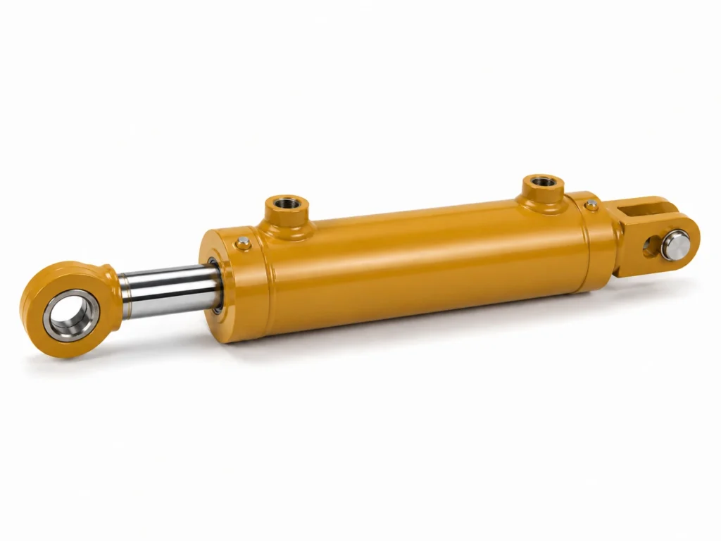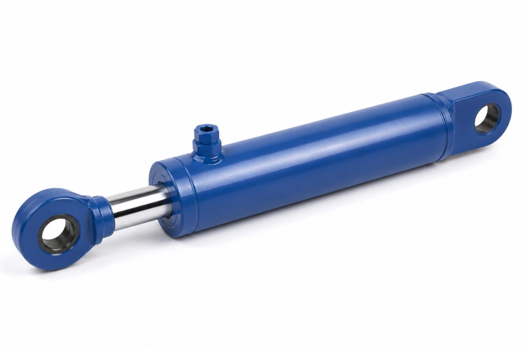
Why do cylinders fail to lift even when the formula looks correct?
A cylinder usually fails in the field because the calculation stopped at theoretical force and ignored friction, pressure drop, rod-side area, side loading, or load spikes. For an engineering buyer sizing equipment, the correct decision is not the smallest bore that works on paper; it is the smallest bore that still works after real losses and safety margin are included.
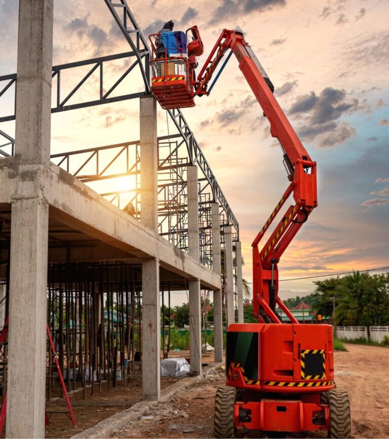
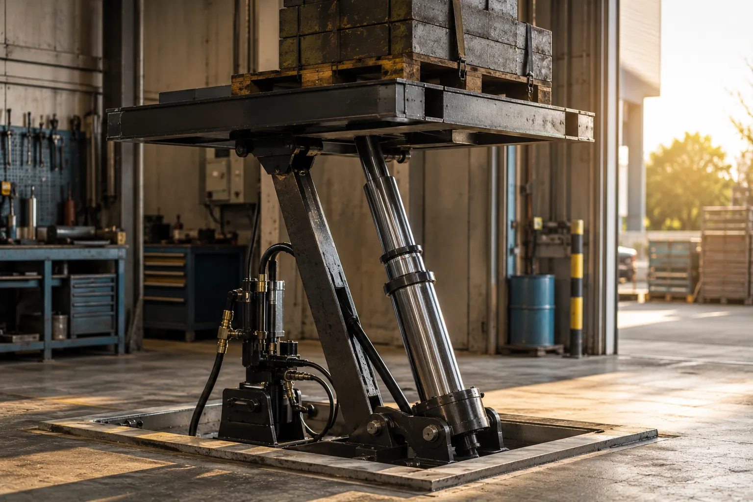
Consider a compact lifting table specified for a 4,000 kg payload. A quick calculation may show that a 100 mm bore cylinder can lift the static load at the available pump pressure. But the table does not lift only a clean static load. It must overcome seal friction, pivot geometry, uneven loading, acceleration, hose losses, valve pressure drop, and sometimes cold oil viscosity. If the calculated force is close to the required load, the bore is already too optimistic unless the equipment has a separate mechanical advantage or confirmed operating pressure reserve.
This is why the decision logic should be strict: if calculated force is less than the required load plus margin, increase bore, increase pressure only if the whole system is rated for it, or redesign the linkage. If the calculation is barely above the load, choose margin first. Increasing pressure without checking hoses, valves, seals, mounts, and standards compliance can move the risk from “will not lift” to “unsafe system.”
For ZHY customers, the most useful starting data is simple: load, operating pressure, stroke, mounting style, duty cycle, available space, and whether the cylinder pushes or pulls. With those inputs, a bore estimate can be checked against real operating conditions rather than treated as a catalog guess.
What is the basic hydraulic cylinder force formula?
The basic answer is direct: force equals pressure multiplied by effective piston area. For extension, use full bore area. For retraction, subtract rod area from bore area. That difference is where many wrong bore choices begin, especially when buyers assume push and pull force are the same.
The standard hydraulic cylinder force formula is:
Force = Pressure × Effective Area
In inch-pound units, if pressure is in psi and area is in square inches, force is in pounds-force:
F(lbf) = P(psi) × A(in²)
In metric units, if pressure is in pascals and area is in square meters, force is in newtons:
F(N) = P(Pa) × A(m²)
A practical metric shortcut is:
F(kN) = Pressure(bar) × Area(cm²) × 0.01
For bore area, calculate:
Bore Area = π × Bore Diameter² ÷ 4
For rod-side retraction area, calculate:
Retract Area = π × (Bore Diameter² − Rod Diameter²) ÷ 4
If you need to calculate the force in hydraulic cylinder selection for a machine that both pushes and pulls, check both directions. A 100 mm bore with a 50 mm rod has about 78.5 cm² extension area but only about 58.9 cm² retraction area. At 160 bar, theoretical extension force is about 125.7 kN, while theoretical retraction force is about 94.2 kN before losses. That is a large difference for clamps, gates, ejectors, and return strokes.
- Bore
- The internal diameter of the cylinder barrel; it determines piston area and is the main driver of push force.
- Rod Diameter
- The diameter of the chrome rod attached to the piston; it reduces effective area during retraction and affects buckling resistance.
- Effective Area
- The area actually exposed to pressure in the direction of movement; full bore area for extension and annular area for retraction.
- Safety Margin
- Additional force capacity above the calculated load to cover friction, pressure loss, shock, wear, and uncertainty in field conditions.
Key Takeaways
- Use pressure multiplied by effective area, not nominal cylinder size, to calculate theoretical force.
- Retraction force is lower than extension force because the rod area reduces the working area.
- If theoretical force is close to the required load, increase bore or margin before approving production.
- Pressure loss, seal friction, linkage geometry, and cold oil can prevent a cylinder from lifting in real service.
- Check bore size together with rod buckling, mounting strength, stroke, duty cycle, and system-rated pressure.
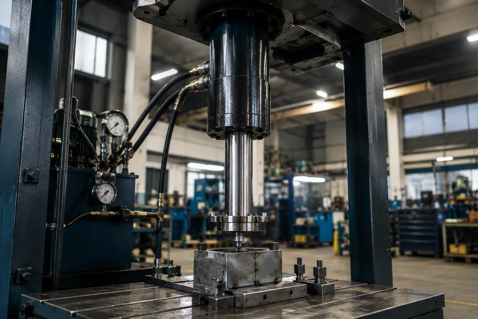
How do you choose bore size after calculating force?
Choose bore size by converting required load into required effective area, then selecting the next standard bore that provides enough force after losses. If the calculated bore is between two catalog sizes, the correct choice for lifting and safety-critical work is normally the larger bore, unless space, speed, or oil flow limits make redesign necessary.
The sequence is straightforward. First, convert the load into force. A 5,000 kg vertical load is approximately 49.0 kN before friction or acceleration. Second, divide the required force by available working pressure to obtain minimum piston area. Third, convert area into bore diameter. Fourth, apply an efficiency and safety margin. Finally, select a standard bore from the manufacturer’s available range and verify the rod diameter, stroke, and mounting style.
For example, assume a machine must lift 60 kN and available pressure at the cylinder is 160 bar. The theoretical area required is 37.5 cm² because 160 bar × 37.5 cm² × 0.01 = 60 kN. This area corresponds to a bore of about 69 mm. A 70 mm bore looks close, but it leaves little room for losses. An 80 mm bore has about 50.3 cm² area and produces about 80.4 kN theoretical force at 160 bar. After a 15% allowance for losses, usable force is about 68.3 kN, which is much more credible.
What efficiency and safety margin should be used in real projects?
Use theoretical force for the first estimate, then reduce it for real system losses and compare the remaining force against the required load plus safety margin. For steady, guided industrial motion, a moderate margin may be enough. For lifting, shock, off-center loading, cold starts, or outdoor equipment, use a larger margin and verify the structure.
Hydraulic cylinders lose usable force through seal friction, side load, imperfect alignment, valve pressure drop, hose length, flow restrictions, and temperature-related oil behavior. The exact loss depends on seal design, lubrication, bore finish, speed, contamination, and operating pressure. Because many of these variables are installation-specific, buyers should not treat a catalog force table as guaranteed field output.
Standards such as ISO 4413 set general safety requirements for hydraulic fluid power systems, while ISO 3320 defines metric series for cylinder bores, piston rods, and area ratios. These standards do not replace application engineering, but they help buyers avoid nonstandard dimensions and unsafe assumptions. For pressure-containing systems, every component in the hydraulic circuit should be rated for the selected pressure, including hoses, fittings, valves, manifolds, gauges, and cylinder ports.
| Operating situation | Typical risk | Recommended sizing response | Buyer priority |
|---|---|---|---|
| Steady horizontal push with guided load | Low friction variation if alignment is controlled | Use calculated force plus moderate margin and confirm guide rails | Compact bore and controlled speed |
| Vertical lifting platform | Load cannot lift or may drift if force reserve is too small | Select the next larger bore when calculation is close to the required load | Lift reliability and safety reserve |
| Clamping fixture or press | Actual clamp force may be lower due to pressure drop and seal friction | Verify pressure at the cylinder port and use force gauge testing where possible | Repeatable output force |
| Mobile equipment with shock load | Dynamic impact can exceed static calculation | Increase force margin and check pins, mounts, rod buckling, and relief settings | Durability under field abuse |
| Long-stroke pushing cylinder | Rod buckling may control design before bore force does | Check column strength and mounting style before increasing pressure | Rod stability and service life |
How to use this table: match the row to the dominant operating condition, then prioritize the last column; when two options are close, choose the response that protects lifting reliability, rod stability, or repeatable force rather than the smallest bore.
How does bore size affect speed, oil flow, and machine layout?
A larger bore gives more force at the same pressure, but it also needs more oil volume for the same stroke. That means slower movement if pump flow stays unchanged, higher oil consumption per cycle, and sometimes larger valves, hoses, and reservoirs. Bore size is therefore a force decision and a system-capacity decision at the same time.
For a 500 mm stroke, an 80 mm bore cylinder has about 2.51 liters of extension volume. A 100 mm bore cylinder has about 3.93 liters for the same stroke. If pump flow is fixed, the larger bore will extend more slowly. This trade-off matters for automated fixtures, presses, dump mechanisms, and production equipment where cycle time affects output.
Space is another constraint. A larger bore increases outside diameter and may require larger clevises, pins, brackets, and guards. On compact machines, the buyer may need to compare three choices: increase bore, increase pressure within rated limits, or change the linkage geometry so the cylinder has better mechanical leverage. The safest route is not always the largest cylinder; it is the configuration that reaches required force without exceeding pressure ratings, rod stability, or available installation space.
In procurement discussions, ask the supplier to show both force and speed. A quotation that only lists bore and stroke is incomplete for engineering approval. ZHY typically recommends confirming the pressure available at the cylinder port, not only pump relief pressure, because long hose runs and valves can reduce working pressure at the actuator.
What real-world examples show the right bore-size decision?
Real machines rarely fail because the equation is unknown; they fail because the equation is used without context. The following examples show how calculated force, pressure margin, and installation conditions change the bore decision.
Example 1: Industrial lift table with limited pump pressure
A facility engineer needs a cylinder to raise a loaded platform. The static payload is known, but the load can sit off-center and operators may start the lift in cold conditions. The first calculation shows a bore size that meets the static load at nominal pump pressure. That is not enough. The better decision is to size using pressure available at the cylinder, include friction in pivots, then move one bore size up if usable force is close to the payload requirement.
This example favors reliability over compactness. If the bore is increased, the buyer must also check cycle time because the same pump flow fills a larger piston area more slowly. If speed becomes unacceptable, a higher-flow pump or revised linkage may be needed instead of forcing the original bore to work at its limit.
Example 2: Press fixture where repeatable clamping force matters
A production fixture may require a specific clamping force to hold a workpiece without deformation. Here, oversizing the bore can create a different problem: excessive clamp force if pressure is not regulated. The right solution is to calculate force, choose a bore that gives adequate force at a controlled pressure, and use pressure regulation or measurement to protect the part.
For this application, the buyer should ask for seal type, bore finish, test pressure, and leakage criteria. Repeatability matters more than maximum force. A well-matched cylinder with verified pressure control will outperform an oversized cylinder that crushes parts or causes fixture deflection.
Example 3: Long-stroke mobile cylinder exposed to side load
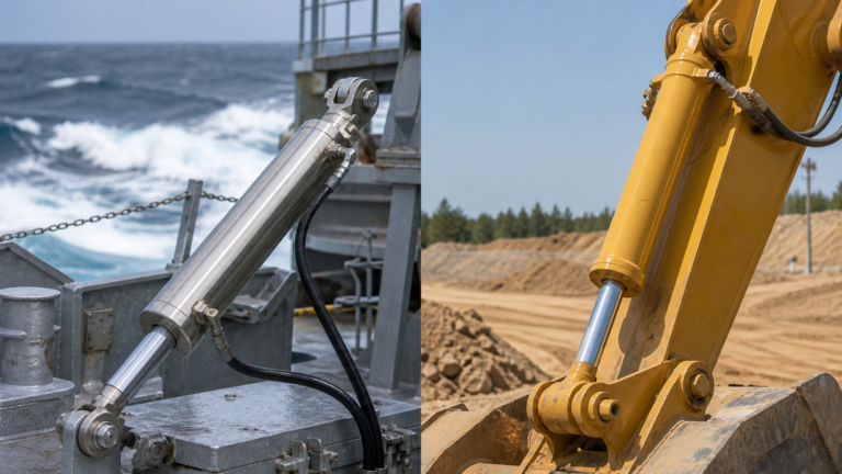
Mobile equipment often creates side load through changing angles, dirt, shock, and uneven ground. A simple force calculation may say the bore is large enough, but the rod may still be vulnerable to bending when extended. In this situation, rod diameter, mounting style, guide support, and buckling check can matter as much as bore area.
The correct decision is to calculate push force first, then check rod stability at the worst extension length and load angle. If rod buckling is the limiting issue, increasing bore alone may not solve the problem. A larger rod, shorter unsupported length, improved guides, or revised mounting geometry may be required.
What standards and compliance checks matter before ordering?
Before ordering, check whether the cylinder dimensions, pressure rating, mounting interface, and safety assumptions align with recognized hydraulic standards and local machinery safety requirements. Standards do not calculate your load for you, but they reduce dimensional confusion and help define safe hydraulic system design.
ISO 4413 is widely referenced for general rules and safety requirements for hydraulic fluid power systems and components. ISO 3320 covers metric cylinder bores, piston rod diameters, and area ratios, helping buyers communicate standard sizes rather than custom guesses. ISO 6020 and ISO 6022 series standards cover mounting dimensions for selected hydraulic cylinder pressure classes, which is important when replacing cylinders or designing around standard envelopes.
For buyers, the practical compliance checklist is simple. Confirm working pressure and test pressure. Verify that the cylinder, hose, fittings, valves, and relief settings are rated for the same system envelope. Ask whether the bore and rod dimensions follow a recognized series. Confirm that the mounting style can handle the expected force without bending pins or tearing brackets. For lifting equipment, include load-holding valves, controlled lowering, and risk assessment according to the applicable machinery rules in the market where the equipment will be used.
What should you ask a supplier before approving the bore size?
Ask for the information that proves the cylinder will work in the real circuit, not only in a catalog table. A supplier should be able to confirm bore, rod, stroke, pressure rating, seal choice, mounting dimensions, test process, and packaging protection before mass production.
For an engineering buyer, the best supplier response includes a calculation sheet or force confirmation, a drawing with mounting dimensions, pressure test records, and clear assumptions about pressure and load direction. If the supplier cannot tell you whether the quoted force is extension force or retraction force, the quotation is not ready for approval.
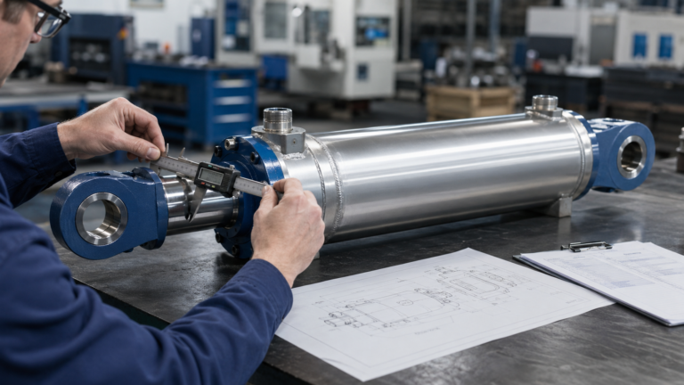
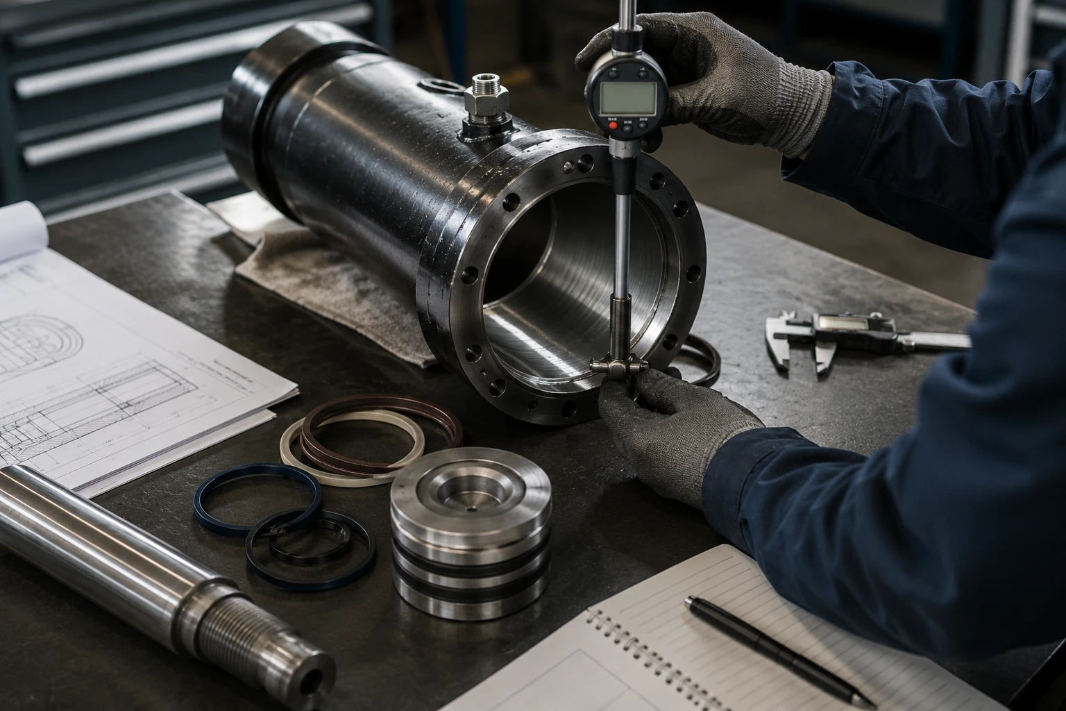
The most useful drawing details include bore, rod diameter, stroke, closed length, port size, mounting type, pin diameter, seal material, surface treatment, and allowable pressure. For repeated procurement, request batch consistency controls such as bore inspection, rod surface inspection, seal verification, weld inspection where applicable, and final pressure testing. These steps reduce the chance that a cylinder that worked in the sample stage fails in the first production batch.
Practical Asset: bore-size verification checklist before purchase
Use this sequence before approving a hydraulic cylinder order. It is designed for buyers who already know the load and available pressure but want to avoid selecting a bore that cannot lift, clamp, or return under real operating conditions.
- Write down the real load case first: maximum load, direction of force, vertical or horizontal motion, static or dynamic duty, and whether the cylinder pushes, pulls, or does both.
- Ask the machine team for pressure available at the cylinder port, not only pump relief pressure. If that value is unknown, request a gauge test point near the actuator.
- Calculate extension force using bore area and retraction force using bore area minus rod area. Record both values if the cylinder must work in both directions.
- Subtract a realistic allowance for seal friction, valve loss, hose loss, side loading, and temperature effects. Use a higher allowance for lifting, shock, outdoor work, or poorly guided loads.
- Compare usable force with required force. If the two values are close, do not choose the smaller bore. Increase bore or redesign the linkage after checking available installation space.
- Check rod diameter for buckling when the stroke is long or the cylinder pushes while extended. Do not approve the bore until rod stability is reviewed.
- Request a drawing showing bore, rod, stroke, closed length, mounting style, port size, and pin dimensions. Confirm these dimensions match the machine envelope.
- Ask the supplier for pressure rating, proof test method, seal material, rod coating, and leakage inspection. These items affect real force and service life.
- Confirm the hydraulic circuit includes relief protection and load-holding controls where lifting or suspended loads are involved.
- Send the final load, pressure, stroke, mounting, and duty-cycle data to the supplier for written force confirmation before placing a bulk order.
FAQ
1. How do I calculate hydraulic cylinder force in simple terms?
Multiply hydraulic pressure by the effective piston area. For extension, effective area is the full bore area. For retraction, subtract rod area from bore area before multiplying by pressure. In metric work, a practical shortcut is force in kN equals pressure in bar multiplied by area in cm² multiplied by 0.01. After that, reduce the theoretical result for system losses and compare it with the load plus safety margin.
2. Why is my cylinder not lifting even though the calculated force is enough?
The most common reason is that the calculation used theoretical pump pressure and ignored real losses. Pressure at the cylinder may be lower because of valves, hoses, fittings, flow restrictions, or relief settings. The load may also be higher than expected due to friction, side loading, linkage angle, acceleration, or cold oil. If calculated force is only slightly above the load, the cylinder may fail to lift in real service.
3. Should I increase bore size or increase hydraulic pressure?
Increase bore size when the force calculation is close to the required load and the machine has enough space and acceptable speed. Increase pressure only when every component in the hydraulic circuit is rated for the higher pressure, including cylinder, hoses, fittings, valves, seals, gauges, and mounts. For lifting equipment, bore margin is usually the safer first option because pressure increases can create wider system safety risks.
4. Is push force always higher than pull force in a hydraulic cylinder?
In a single-rod hydraulic cylinder, push force is normally higher than pull force because extension uses the full bore area, while retraction uses only the annular area around the rod. The rod occupies part of the piston area on the retract side. This difference can be significant on cylinders with large rods, so buyers should calculate both directions when sizing clamps, ejectors, lifting arms, gates, or return strokes.
5. What information should I send to ZHY for force confirmation?
Send the required load, operating pressure at the cylinder, stroke, push or pull direction, mounting style, available installation space, duty cycle, working temperature, and whether the load is guided or side-loaded. If you have a drawing, include bore, rod, port size, closed length, and pin dimensions. With these details, ZHY can check theoretical force, usable margin, rod stability, and whether a larger bore or different configuration is needed.
References
- Hydraulic Fluid Power — General Rules and Safety Requirements for Systems and Their Components, International Organization for Standardization, ISO, 2010.
- Fluid Power Systems and Components — Cylinder Bores and Piston Rod Diameters and Area Ratios — Metric Series, International Organization for Standardization, ISO, 2013.
- Hydraulic Fluid Power — Mounting Dimensions for Single Rod Cylinders, 16 MPa Series — Part 1: Medium Series, International Organization for Standardization, ISO, 2007.
- Hydraulic Fluid Power — Mounting Dimensions for Single Rod Cylinders, 25 MPa Series, International Organization for Standardization, ISO, 2018.
- Industrial Hydraulic Cylinders Catalog HY08-0910, Parker Hannifin Corporation, Parker Hannifin, 2023.
- Hydraulic Cylinders Project Planning Manual, Bosch Rexroth AG, Bosch Rexroth, 2023.
- Basic Hydraulics and Hydraulic Principles, Enerpac Tool Group, Enerpac, 2024.
- Fluid Power Data Book, National Fluid Power Association, NFPA, 2023.
Semantic Closing: how force calculation becomes a better cylinder-buying decision
The best way to size a hydraulic cylinder is to treat force calculation as the beginning of engineering judgment, not the end. The formula explains the physics: pressure acting on area creates linear force. The purchasing decision must go further by asking whether that force remains available after real losses, whether the bore fits the machine, whether the rod survives the stroke, and whether the hydraulic circuit is safely rated.
For buyers searching how to calculate hydraulic cylinder force, the most important shift is from “What force can this cylinder make?” to “What usable force will this cylinder deliver in my machine?” That wording changes the decision. It forces the engineer to check cylinder-port pressure instead of pump nameplate pressure, push and pull areas instead of bore alone, and force reserve instead of minimum theoretical output.
Industry practice is also moving toward more application-specific hydraulic selection. Compact machines, automated fixtures, and mobile platforms all demand higher force density, but customers also expect predictable motion, safer load control, and easier maintenance. Standards such as ISO 4413 and ISO 3320 help frame safe hydraulic system design and standard dimensional communication, while manufacturer catalogs from Parker, Bosch Rexroth, Enerpac, and other hydraulic specialists show why pressure rating, mounting, seals, and rod design must be considered together.
The clear recommendation is this: if calculated force is comfortably above the required load after losses and margin, keep the bore compact and verify speed. If calculated force is close to the required load, do not force the smaller bore into the design. Increase bore, improve mechanical leverage, or confirm a safely rated pressure increase. If the cylinder has a long stroke or side load, check rod buckling before approving the order. This approach protects lifting reliability, reduces warranty disputes, and gives suppliers like ZHY enough data to confirm a cylinder that will work outside the spreadsheet.